Technical Sprinter

Technical Sprinter

Mercedes Sprinter Clutch Pedal Pivot Wear / Removal

 
For a couple of weeks a driver had been complaining that occasionally the clutch pedal on the 2005 LWB Sprinter would stay down lower than it should. He said he could hook his foot under it and pull it level with the other pedals but this was far from satisfactory. When I got into the van the whole clutch pedal layout seemed strange, in fact the pedal was so far over to the left that it was almost touching the vertical part of the centre dashboard console.

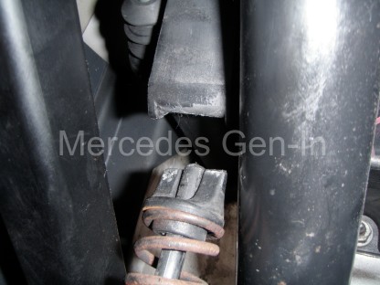
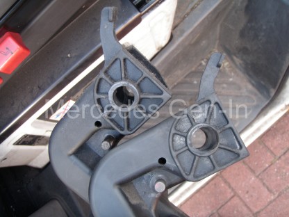
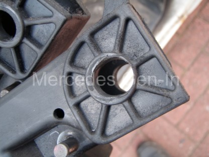
On examination the plastic pedal could be pulled sideways about two inches and a closer look revealed that the shaft pivot moulded into the pedal had worn oval. It had worn away to such an extent that the built up area around the hole that accepts the pivot shaft had almost worn through and begun to crack. We had a spare clutch pedal to fit originally taken from a Luton chassis cab Sprinter, they are the same part across the whole model range.

Mercedes Sprinter Clutch Pedal Wear 1

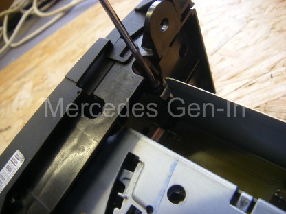
Removal and refitting is straight forward enough – On the left hand side of the clutch pedal steel pivot part of the alloy/steel pedal box assembly, there is a single large spring clip that secures the pedal. Use a broad flat blade screwdriver to lift, slide and release this. Note that there is a thin nylon washer between it and the pedal itself. Retrieve this and keep it safe.

Using a small screwdriver unclip the two circlips on the opposite side of the pedal. One at the top, releasing the master cylinder piston and one at the bottom of the pedal, holding the return spring shaft eye.
Unhook the upper master cylinder shaft and then wiggle the pedal on its shaft towards the left. As soon as the first side cheek of the pedal extends past the end of the shaft, rotate the pedal anticlockwise almost 90 degrees. As you do this, the upper part of the return spring will disengage from the plastic ‘V’ in which it sits and release its tension. You now can remove the pedal return spring assembly and place it to one side.

Mercedes Sprinter Clutch Pedal Wear 2

Continue to unhook the pedal from the pivot shaft and remove it from the pedal box.

Mercedes Sprinter Clutch Pedal Wear 3

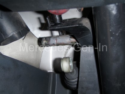
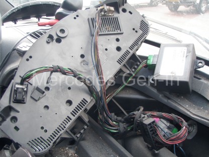
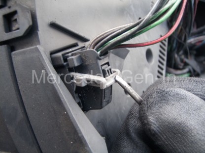
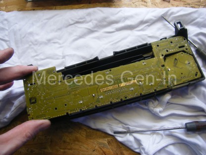
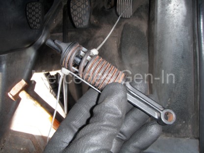
Replacement is straight forward, building the new pedal into place leaving the return spring until last. Remove the coil spring from the return spring assembly and take it to a bench vice. Carefully compress the spring using two spacers, one on each end, to allow access to feed either wire or tie-wraps through the coils as the spring is held in a compressed state. I used an old pair of the square steel shafts that interconnect the door handles on domestic doors, you can use whatever you have available. Once the spring is compressed in the vice, use a pair of good quality cable ties or 1.5mm copper wire to secure the spring in a compressed state. Carefully undo the vice and remove the spring. Assemble the spring onto the return spring rod, building it up as the photograph below. Locate the top plastic pointed tip into the ‘V’ slot that is located on the upper pedal box. Bring the pedal into alignment with the lower eye and slide it onto the shaft. Fit the retaining circip. Using a pair of side cutters, snip the tie-wraps or retaining wire to release the tension on the return spring. Just be aware to keep the top pointed tip aligned in the ‘V’ shaped slot as you release/cut the ties on the spring.  For information: the return spring locating pointed tip and ‘V’ slot, run from left to right – in the same plane as the pedal pivot. Also of casual interest in the photograph above, you can see the electrical switch (in the top part of the picture) that signals the clutch pedal position to the ECU. This can give rise to ‘Limp Home’ problems in the same way as a faulty brake position switch. Ensure that you do not disturb its position or wiring during the pedal replacement procedure.

Mercedes Sprinter Clutch Pedal Wear 4

Once the return spring is back in place you are good to go. Don’t forget to replace the pedal rubber if it worn, this is an ideal time to do this.

Mercedes Sprinter Clutch Pedal Wear 6

Mercedes Sprinter EDC Lamp – Putting right the ‘bodgers’ work

 
From time to time you come across things that just amaze you, and this customers Mercedes Sprinter van was no exception. The van had come in with an obvious ABS fault, sensor wire physically and visually broken, and no warning illumination on the dash. Once the ECU was read there were in fact several faults related to the engine that should have illuminated the EDC lamp too, but nothing!

Mercedes Sprinter Instrument Lamp Repair 1

After a bit of fuse-chasing and voltage checking, it seemed the problem was at the instrument pod end. It turned out the previous owner had removed the instrument pod, unclipped the PCB and prized it apart just enough to slide a small screwdriver in and break off the surface mount indicator LEDs. These should have illuminated showing the current faults. It was hard to say if this was actually a measure to disguise the faults so the vehicle could be sold, through maybe auction or otherwise or if it was a desperate attempt to get the vehicle through the annual MOT – Who knows…   All I knew was that before any other remedial work could be done this sensibly had to be rectified first.

To gain access to the Sprinter instrument pod, first prize off the light grey facia moulding that contains the drivers air vent and switch banks. Tilt this around the steering wheel and let it hang to the floor with switch cables still attached. If you have more options and switches in place on both sides of the steering wheel it is best to label each and remove the electrical connectors from the switch backs, removing the panel completely. Do not be tempted to not mark what comes or goes to where, as several of the switch options have the same plug shape format with only different pin layouts. It is entirely possible you can plug the wrong loom plug into the wrong switch as they will fit!

Mercedes Sprinter Instrument Lamp Repair 2

The removal of the facia reveals two screws either side of the instrument cover, these can be removed and the instrument cover lifted off and out of the way. A further two screws either side of the instrument cluster hold it in place and once removed the assembly can be pulled forward from the top, disengaging it completely. On the rear cover of the cluster you will see two multiway connectors, one grey/white one black. These have a special locking latch mechanism that releases them from the PCB. Just behind the lever on the plug body shell is a small press-in latch, once pushed, the locking release arm can be drawn over it and arced downward to horizontal. The action of moving this lever pulls and ejects the connector from its mating part, enabling it to be easily released and fully disconnected from the cluster. Unlatch both connectors and remove the instrument cluster to a clean work surface or bench.

Mercedes Sprinter Instrument Lamp Repair 3

Around the removed instrument cowl is a series of clips, three at the top and bottom and one each side. Carefully unclip and release these, lightly pulling off the front cover of the instrument pod as you go. Once totally free the back cover can also be pulled from the instrument PCB.

Mercedes Sprinter Instrument Lamp Repair 4

To gain access to the LED indicator lamps you will need to pull off the dial servo motor indicator fingers. Grasp the centre black covers and unclip them, making note at this point of what came from where. Then grip the indicator pointers by their central hub and ‘pinch’ them off the spindles between forefinger and thumb. Be sure not to rotate the gauge stepper motor spindles as the correct position of the pointer will be lost. This will make repositioning the pointers difficult – without further powering up of the instrument cluster to reset the base zero positions, then agin aligning and refitting the indicator needles to accurately point to their associated rest positions.

Once all pointers are removed, the black instrument face can be removed from the PCB. This is done by unclipping a series of protruding white clips at the back of the board. Once these are released the two parts can be separated, revealing the indicator LEDs at strategic points on the front face of the PCB.  Positioned so they illuminate and channel light to backlit icons screen printed on the instrument face.

Mercedes Sprinter Instrument Lamp Repair 5

You can see from the photograph above what state the warning indicators were in and how they had been crudely levered/broken from the board. Fortunately only the LED components themselves had been damaged and not the copper tracks where they were attached. All I needed to do was remove the remnants of the old LEDs and attach new replacements.

Please note:I do have number of new yellow OSRAM SMD ultra-bright LEDs as used in Mercedes Benz consoles and if anyone has similar problems please contact me and I can arrange supply for a modest cost.

Mercedes Sprinter Instrument Lamp Repair 6

If you need to source Mercedes instrument panel LEDs – drop me an email to steve@mercedes.gen.in

Once the new LEDs were soldered in position (fitted to observe the correct diode polarity) the PCB was ready to be reassembled and fitted back into the van. Once reinstalled the ABS fault was rectified and the ECU fault codes cleared. This correctly extinguished the ABS lamps and left the EDC lamp illuminated – correctly warning us of our next engine related problem to be rectified!

Mercedes Sprinter Instrument Lamp Repair 7

This issue truly highlights the importance of any potential Mercedes purchaser testing all the dash lamps in ‘ignition’ position to make sure all lights are illuminating correctly as they should in ‘lamp test mode’ before starting the vehicle. This point could easily be overlooked when buying a vehicle and turn out to be quite a costly oversight, so as you can see is this is a simple but very important check!

Sprinter Starter Motor Replacement

 
For a few days now one of the Sprinter fleet had been failing to start due to what was obviously a starter engagement issue. You would turn the key and most times it would start as normal, then without warning, usually at the most inconvenient of times, it would just whirr and not engage with the flywheel ring gear. Repeated turning of the key eventually cajoled the engine into starting.

We had a replacement used starter motor on the shelf, taken off a defunct engine broken for parts – this was going to be fitted.

The replacement of the starter motor is quite straight forward and quick to do. If you are reasonably slim and dextrous it can just about be done in an emergency at the roadside without jacking the vehicle, for ease it is better to raise the left hand front corner of the van eight or so inches to aid access.

Sprinter Starter Motor Replacement 1

Start by disconnecting the battery and then removing the single reverse torx pin that holds the plastic cable conduit that is bolted above the starter motor. An 8mm hexagon socket will do the trick here if you don’t have the correct torx tool to hand. Disconnect the solenoid lead from the connection stud at the rear of the actuator (solenoid) of the starter motor (10mm spanner). Pull back the black plastic moulded protection sheath covering the battery supply lead nut and remove this too. (13mm spanner) pulling both cables free out of the way of the starter.

Climb underneath the left front of the vehicle behind the front wheel and look up to the bell housing, in the area where the twin gear cable assembly mounts. Here you will see two reverse torx fixings that extend through the gearbox bell housing casting into the faceplate of the starter motor. A short extension bar is essential to negotiate the bowden selector cables up top of the gearbox. The upper fixing is almost out of sight and you may benefit from placing the socket onto the bolt first before attaching the extension and ratchet. Undo the top pin fully and remove it. Extend a hand up in front of the cross member and support the rear of the starter and begin to undo the lower, more accessible torx bolt fixing. Once sufficiently loose, jiggling the starter slightly will assist you to remove the remainder of the lower pin by hand.

Sprinter Starter Motor Replacement 2

From inside the engine bay, extract the starter motor upwards, being careful not to damage any cables as you go.

While the starter is out of the vehicle, inspect the teeth of the ring gear through the open aperture, for wear/damage. If everything is in order, set about fitting the replacement starter motor as an exact reversal of removal.

Sprinter Starter Motor Replacement 3

Often what happens with the starter motor itself is the shaft on which the starter gear slides when actuated by the solenoid gets oil contamination on it, this in turn attracts grit and debris that causes it not to push fully forward and fully engage when activated. All the moving components of a starter motor are un-lubricated and any signs of oil generally spells trouble. We can see this one is oil contaminated from an engine oil leak of some kind over time. Obviously there are many other faults, including electrical and mechanical ones, that can occur inside the motor unit. Often these can be rectified by further dismantling and bench repair or by entrusting the services of a competent auto-electric rebuilder.

Sprinter Starter Motor Replacement 4

Sprinter Low Boost – Limp Home on Full Throttle

 
One of the 2004 long wheel base Mercedes Sprinters developed a problem where everything was fine under moderate throttle openings but once full power was called for, the van would register a fault and lock into limp home. Recycling the ignition cleared the fault, until the next wide open throttle and call for high power.

A great deal of work had been done on this particular van over a short period and most of the regular problematic contenders covered elsewhere on this subject had been dealt with. We knew we had good fuel delivery, good fuel pressure, sound boost and good induction hose-work. New sensors had been fitted on both low and high pressure points on the system and the only fault recorded was low boost.

Faulty Sprinter turbo boost actuator

We had previously seen another fleet operators Sprinter register low boost and discovered that the intake air filter was completely choked with muck and grime, this was not the case with this van.

Examining for mechanical issues became a primary focus as all the electrical systems were sound and cross-referring their readings on ‘live data’ proved their adequate function. In driving the vehicle with the code reader connected, we were able to see that maximum turbo boost was never achieved at full power, but was seen approaching moderate peaks at more modest and lazy throttle openings.

Often the van would perform fine unladen and fail consistently when loaded, slipping into limp home as soon as the driver tried to make good progress.

I removed the airbox and checked the vacuum pipework from the brake servo to the boost control valve and everything was in good order. I removed the supply pipe to the turbo actuator and double checked this for problems such as nicks, cuts and splits – nothing.

The lever arm to the turbo was free and this was confirmed by removing the circlip from the eye of the actuator arm and manually operating it to prove there was nothing wrong within.

Faulty turbo boost actuator Mercedes Sprinter

My next test was to push the actuator rod back into the actuator and be certain the movement was unhindered and smooth. The next test was to block the vacuum pipe opening with a finger, allowing air to be expelled while I pushed the rod inward. Closing the gap with moderate finger pressure should be enough to hold vacuum inside the diaphragm, making a ‘popping’ sound as the rod springs back to its extended position when you release your finger. I noticed the fitted actuator was not doing as it should in that respect as it was not ‘popping back’ to an extended position. Indeed, careful observation proved that the rod was moving very slowly to a fully extended position with a finger blocking the port, indicating a failure of the internal diaphragm – probably a slight leak or pin-hole.

This would under normal circumstances been difficult to spot as it had not failed completely. The actuator still pulled the turbo lever to a fully down position once the engine was started. However the small leak meant that the on-off pulse control of the actuator, given by the Pulse Width Modulation (PWM) of the vacuum control valve, was not as it should have been – resulting in under-boost on high power call situations.

The replacement of the actuator although fairly straight forward in mechanical terms, is a bit of a fiddle to accomplish, as one of the mounting bolts is a good finger-stretch into the confines of the turbo and takes some jiggling to get the pin back into position and tighten it.

There are three 10mm bolts into the exhaust side of the turbo scroll casting. These hold the actuator support bracket and also clamp the spool cartridge face against the turbo scroll casting flange making a gas tight seal.

Once these three bolts are removed and the circlip removed from the rod/lever, the actuator can be removed for inspection. Access to the area is best achieved by removing the complete air box, the turbo intake hose and brake servo vacuum pipe. Once these components have been removed, additional removing the vertical heat plate/shield that separates the air box from the turbo assembly is essential to obtain free access to the three actuator fixing bolts – especially as one is a real swine to get to!

Faulty turbo boost actuator Mercedes Sprinter 2

It is important to set the actuator arm/rod length of the replacement part to the same dimension as the original. This is critical in that it effects how the vanes are positioned within the turbo for any given actuator setting. Simply measure the new rod length to the old one and make adjustments using the 10mm lock-nut and thumbwheel provided on the actuator rod. Lock the setting once you have it and ensure the hole in the rod eye is positioned in the correct plane to accept the lever bar of the turbo once reinstalled.

Rebuild is the reverse of disassembly from this point. Once fully built, check your work and clear any remaining fault codes and then road test the vehicle. Once again boost should be available through the complete power range and it should react smoothly to engine loading, just as it did prior to the fault occurring.

Other Mercedes Sprinter turbo fault/boost related posts:

http://www.mercedes.gen.in/WP35/mercedes-sprinter-turbo-limp-home-los-diagnosis-fault-finding/
http://www.mercedes.gen.in/WP35/new-turbo-still-boost-mercedes-sprinter/
http://www.mercedes.gen.in/WP35/not-maintaining-sprinter-air-filter-can-leave-stranded/
http://www.mercedes.gen.in/WP35/diesel-mercedes-sprinter-turbo-rebuild/
http://www.mercedes.gen.in/WP35/mercedes-sprinter-turbo-blown-symptoms/
http://www.mercedes.gen.in/WP35/mercedes-sprinter-t1n-large-engine-oil-loss-leak/

Please be sure to use the comprehensive site search facility to find what you are looking for (Just enter your search term in the search box on the top right and click search) – There are many informative Mercedes posts on this this site, just waiting to be viewed!

Inside the Mercedes Sound 5 CD/Radio Unit – (Intermittent Buttons, Strange Display Behaviour)

 
Mercedes Sound 5 Radio Repair 1

The Mercedes Sound 5 fitted to Vito and Sprinter vans is a generally reliable unit that performs adequatley for the most part within the environment of a commercial vehicle.  There has been two manufacturers that have produced the radio, Hyundai and Becker.  Although the units are similar in function there are some physical differences to the layout and choice of internal components. Both offer similar audio features and identical connections, designed and produced in alternate factories.

There are few reported problems with either model of the Sound 5 unit, but there are a couple of common issues that crop up from time to time.

The faults: The occasional loss of display and button functionality is the most seen fault and in most cases can be easily rectified by following the procedure outline in this post.  The chassis of the Becker radio is shown in the photographs below and it comes apart in a very simple way.  First lift up and remove the upper steel cover lid by levering at the back.  Identify and remove the two torx head screws either side of the front upper chassis just behind the front panel.  Pull either side of the chassis sides outward to disconnect the latches either side of the front panel.  Lever the front down and off the chassis.

Mercedes Sound 5 Radio Repair 2

What this now reveals is the common cause of the above problems, poor connection between the chassis electronics and the front panel.  There is a row of gold contacts on the Becker made radio that mates with a sprung leaf type chassis connector strip.  This connector carries all the communications from the front panel to the micro controller mounted on the chassis PCB.  There is a multiplexed communications bus that sends and receives commands to and from the front panel, causing buttons to have actions and the display to illuminate whatever the CPU tells it.

Mercedes Sound 5 Radio Repair 3

Corrosion due to the damp (condensation) environment in which the radio lives, begins to tarnish the connections between the chassis and front panel.  The panel PCB’s plated pads take on board some discolouration / oxidisation, as do the mating tips of the sprung leaf contacts.  To maintain a good connection between the two assemblies is important, as the communication and functionality of the radio depend on it.  When these contacts become less reliable a catalogue of faults can start to appear.  These faults are usually – Buttons do not function as they should, it becomes impossible to turn off the radio, the display inverts or displays nothing, except the amber back light.  Even sometimes resetting with the ignition does not always bring back the radio to a working condition.

Mercedes Sound 5 Radio Repair 5

With the front panel face down on a soft cloth, remove all the self tapping torx screws on the rear, carefully unclip the four plastic tabs, one on each corner of the lower and upper edges.  Once the plastic back panel has been lifted off, turn over to the front and grasp the volume ring by its edges, giving it a straight pull.  The volume ring and ‘on’ button will unlatch, keep them safe.  It is now possible to remove the PCB from the button matrix mounted in the front part of the housing.

Mercedes Sound 5 Radio Repair 6

I had a damaged LCD display in the radio I was repairing, no doubt caused by someone pressing or banging the radio front to get it to display correctly.  I have tried to source spare parts from Becker and Hyundai for both models of radio and as yet have had no success getting individual LCD display parts.  What I had managed to do, was source another radio with a faulty chassis quite cheaply.  I was going to exchange the front panel PCB between the two units, as the good LCD display was housed in a case that was more worn and grubby than my own.  By changing over just the display unit in the front panel I was preserving the chassis security coding that is mated to the ECU in the vehicle.  If I had just fitted another radio, I would have had the ‘PROD’ error as described here in this post, and the radio would not have functioned.

Mercedes Sound 5 Radio Repair 7

If there had been liquid (soft drinks especially) spilled on the preset buttons at some time and they have become ‘sticky’ and do not return to their normal position – while the front panel is in pieces, it is a simple task to clean this off and have the radio working as good as new.  Once the PCB section is taken out of the front panel it can be seen that the faceplate houses some ‘rubber membrane’ push button pads.  These contact with conductive areas on the front side of the PCB allowing a button press to transmit a function to the processor.  The plastic buttons just provide a means of pushing the conductive rubber membrane against a circuit board ‘pad’.  Once the membrane is removed the buttons can also be unlatched if required and washed in mild detergent.

Mercedes Sound 5 Radio Repair 8

Simply peel back the rubber membrane in one of the three obvious active sections and push the protruding button stems back through to the front of the panel with a thumbnail, thus removing them for cleaning.  If you were to photograph the front panel before disassembly you could remove all the buttons from the facia frame and wash them all in soapy water, leaving them in a warm place to completely dry before building it back up as per your image.  If the rubber membranes are contaminated, wash these very gently, taking care not to use any solvent or abrade the conductive tip areas on the rubber pads.  Similarly, allow these to dry thoroughly before refitting and building up the front panel.

Mercedes Sound 5 Radio Repair 9

The main contact pads areas on the rear of the front PCB were cleaned using a fine cleaning rubber block (you can use a pencil eraser) until bright and shiny, the same was done to the sprung contact leaves on the main chassis, and the front panel rebuilt then fitted back to the chassis.  Be sure to latch the lower edge of the front panel under the chassis lip before folding back the front panel to its fitted, engaged position.

Fitting the two side retaining screws completes the front panel mounting.

Mercedes Sound 5 Radio Repair 10

If you wished to swap-out the CD deck, it is very easy to accomplish before refitting the front panel.  Simply undo the four screws at each corner of the deck and lift it upward.  This reveals a single ribbon cable with red connector to the main PCB.  Pull upward the connector and release the CD deck from the chassis.  A new or replacement assembly can be fitted quickly in the reverse order.

Mercedes Sound 5 Radio Repair 11

Hyundai HA1111 Sound 5 – Top Becker Sound 5 – Bottom.

The Hyundai made radio chassis has some differences from the Becker model, namely the front panel has extra function legends visible above the preset numbers and also the rear panel alloy casting is slightly different.  The photograph below shows the Hyundai HA1111 radio, with its ISO plug connected for identification.  Although the CD deck can be swapped between models, with the exception of maybe the volume control knob and a few plastic bits, that is as far as it goes with regard common parts.  The Hyundai front panel PCB contacts the chassis using pointed pins set in an offset pattern, and as such the two facias are not interchangeable.   It worth noting however that the Hyundai player suffers the same contact oxidisation issues as the Becker model and it can be cleaned and serviced in the very same way.

Mercedes Sound 5 Radio Repair 12

Becker Sound 5 – bottom radio, Hyundai Sound 5 – top radio

Quite often this simple procedure is all that is needed to recover your radio to working condition and it is well worth the simple work involved.

You can of course get to check out and test all the pixels and test the contrast of the LCD display by entering the ‘test’ mode, where you will be able to make other key adjustments and changes, for example: activating the AUX feature if required, to utilise the radios auxiliary audio input capabilities with an external MP3 player etc. See this post here.

Mercedes Sound 5 Radio Repair 14