Technical Sprinter

Technical Sprinter

Mercedes ML W164 V6 Diesel engine tapping under load

Investigating a problem with a good friends Mercedes ML MY2006 320CDI who had noticed a heavy tapping noise from the engine under under anything above moderate load. It sounded expensive

Just like a top end rattle similar to a noise which would be if there if there was an issue with a piston, little-end or ring/gudgeon. Nothing could be heard at idle, which was odd in itself. Lifting the engine revs slowly, whilst stationary, would result in a smooth increase in RPM without the accompanying tapping noise. He reported that performance was down a little too, feeling that top end maximum speed would be unattainable, he was right.

I noticed the service indicator was illuminated on the dash and the mileage rested at some 3500 miles over when the oil should have been routinely dropped. Still, dirty oil alone wouldn’t usually cause a sound like this, but we needed a baseline to work with. A full engine service was carried out, including the twin air filters which frankly looked like leafy undergrowth! The diesel filter was replaced, filling the new one to the brim with a branded diesel system cleaner. The owner had already added ‘in-tank’ cleaners, thinking it could be an injector related noise but without a positive result. Once the neat diesel cleaner had been forced through the direct injector system the car was taken out for a test drive. The noise was still apparent, whenever you pushed the pedal in determination, there would be a tapping soundtrack running parallel to the normal induction noise of the engine.

I started thinking about the noise. Although the tapping was following the RPM rotations of the engine it was not every rev. It was audibly about half the frequency of the indicated RPM on the tacho. As a 4 stroke engine (Diesel or Petrol) does 2 full revolutions per combustion cycle, it was easy to determine it was either injector or valve related. It was highly unlikely that a con rod little end would only knock once every two revolutions of the engine, especially as the forces on the piston would be either dragging it up or down the bore, changing linear direction twice per revolution. I know that sometimes noises only occur on the power stroke when forces are a maximum, but this noise was far lighter than you would expect from a bearing surface that was failing or wearing oval.

The above video illustration explains nicely what I mean. It was most probably an issue with something valve or cam related or as the owner had wondered, an injector.

I dug a little deeper into the engine, removing the plenum and air filter housings to physically inspect the injectors with a good torch. I was looking for the infamous ‘Black Death’ (see video linked below) that often plagued more commonly the earlier 4 and 5 cylinder diesel types as you would see in the T1N Sprinter and many MB passenger cars of the time. The Mercedes OM642 V6 power plant has been known to suffer similar issues with combustion gasses leaking past the injector seals, in some cases making a clicking/tapping sound under load and causing a hard, often shiny black carbon build up around the mating surfaces of where the injector body enters the head (injector pocket)- nothing found!

After running the ML for a few more miles there would be occasions where the tapping-under-load noise would mysteriously disappear. That was great news. Noise from the mechanical failure of a con rod, piston or camshaft would not usually come and go, so that narrowed the field splendidly.

More ‘Italian tune-up’ accelerations and driving style where conditions allowed, over the following week in the hands of ML’s owner, saw the noise diminish and vanish completely over a period of about 10 days.

So, what was it!

I suppose we will never know for sure, but here is my view:

Considering all of the above, noise and lack of sparkling performance, it could have been either – A sticking hydraulic tappet that was suffering from the lack of lube from dirty or plain old worn-out oil, or the lifter just not filling to full pressure due to sludge etc?

Or was it a dirty Piezo diesel injector that was simply misfiring and not performing correctly under load?

This tale goes to illustrate that you should always give a little time to your diagnosis before jumping in with both feet and undertaking what could well turn out to be costly, fruitless unnecessary work.

Everyone was happy with the outcome on this occasion. My advice: Look, listen, make some changes, WAIT a while and observe!

Sprinter / Crafter Clutch Master Cylinder Replacement

Mercedes Sprinter 2006-on and Volkswagen Crafter Clutch Master Cylinder Replacement.

Mercedes Sprinter Crafter Clutch Master Cylinder Swap 1

Having recently replaced the clutch and slave cylinder on a Crafter CR35 with a LUK Rep-set, the driver complained that whilst setting off the clutch seemed fine, after a short period of ‘town driving’ the clutch became difficult to disengage.
What this actually meant was there did not appear to be enough travel in the pedal to fully clear the clutch and pressure plate – meaning there was ‘drag’ after the initial ten or more clutch presses of the day. This drag in turn made gears difficult to engage and at some point even disengage/pull out of gear, with the clutch pedal hard to the floor. Drive take up seemed to begin right down at the bottom end of the pedal travel.

Mercedes Sprinter Crafter Clutch Master Cylinder Swap 2

Having re-bled the system to ensure there was no air lurking in the system, I decided that the clutch master cylinder was at fault, possibly passing pressure and not allowing the full capacity of hydraulic fluid to be transmitted into the slave cylinder, shortening its stoke acting onto the pressure plate spring. It is worth noting that I had previously correctly ‘set’ the clutch cover plate assembly tension as described during installation described elsewhere on this site, so could confidently discount that as being any issue.

Mercedes Sprinter Crafter Clutch Master Cylinder Swap 3
The replacement of the clutch master cylinder, whilst being a little bit awkward to get to, is quite a straight forward job and can be easily attended to in just over an hour – start to finish.

Mercedes Sprinter Crafter Clutch Master Cylinder Swap 4
The first thing to do is remove the hydraulic feed pipework to the clutch master cylinder from the shared brake/clutch master cylinder reservoir. There is a semi-rigid, ribbed plastic pipe that feeds the cylinder fed from a spigot on the side of the brake master cylinder fluid reserve. Work this off gently, quickly pushing on a suitable size ‘blanking’ hose to stem the hydraulic fluid flow. A short length of flexible rubber hose, bent double at the end and secured with a tie-wrap is an ideal temporary blanking plug. Any fluid drips while doing the change over can be caught in a rag placed beneath the spigot.

Mercedes Sprinter Crafter Clutch Master Cylinder Swap 1
Mercedes Sprinter Crafter Clutch Master Cylinder Swap 5
The next pipe to remove is the rigid steel high pressure pipe from the nose of the master cylinder. This connection protrudes into the engine side of the bulkhead to the right and slightly below the centre of the brake vacuum reserve (Right hand drive vehicles). To release the pipe from the master cylinder there is a small retaining clip that has to be pulled downward to release the high side hose. Its a fiddle to get at, but is best attended to with a 90 degree pick or suitable small screwdriver. Note – the clip is ‘retained’ and only pulls down about 10mm to release the pipe, once the pipe is removed, push the clip back up to the locked position so it can be pulled through the bulkhead grommet from the inside without fouling. Once the clip is pulled down, the pipe is released by grasping it and pulling outward, again be prepared for a little fluid leak.

Mercedes Sprinter Crafter Clutch Master Cylinder Swap 1
Mercedes Sprinter Crafter Clutch Master Cylinder Swap 7
Now both feed and delivery pipes are disconnected attention can be drawn to the inside the drivers footwell pedal box area. First remove the circlip and peg that retains the master cylinder rod and eye to the clutch pedal, again a 90 degree pick works well to do this with the restricted space available. Now remove the two 10mm nuts that hold the twin through-pins holding the master cylinder to the pedal box frame. The opposite end to the nut is an E10 reverse torx, which will need to be held whilst undoing the two nuts. Slide both pins out from the pedal box towards the centre of the vehicle, once this is done grasp the master cylinder and pull it downwards and out into the footwell. Only pull the cylinder sufficiently to access the feed pipe spigot and ribbed hose which can be removed in the same way as the other end on the under bonnet brake/clutch reservoir. Once this is off, the cylinder can be taken from the vehicle.

Mercedes Sprinter Crafter Clutch Master Cylinder Swap 8
Unbox the new master cylinder checking that is the correct part, remove its protective blanking plugs and offer it into the footwell, reconnecting the reserve feed pipe. Have an assistant gently pull the ribbed pipe back through the bulkhead grommet as you carefully feed the cylinder body back into position between the faces of the pedal box bracket. As it nears the correct position, use a suitable sized allen wrench to align the through-holes for the two fixing pins. When aligned, slot back the two pins and secure them using the E10 and 10mm wrenches. Feed in the eye of the actuator rod between the faces of the plastic pedal lever, aligning both parts to allow you to push through the peg and refit the retaining circlip.

Mercedes Sprinter Crafter Clutch Master Cylinder Swap 9
Mercedes Sprinter Crafter Clutch Master Cylinder Swap 10
From the engine bay, reconnect the high pressure pipe to the master cylinder nose. Just push the pipe in with its tapered seal until it ‘snaps’ locked in the set spring clip. Now remove the temporary bung and replace the fluid feed pipe back onto the reservoir spigot, checking for correct fitment and attending to any leaks.

Mercedes Sprinter Crafter Clutch Master Cylinder Swap 11
Mercedes Sprinter Crafter Clutch Master Cylinder Swap 12
Connect up a pressure bleeding system such as the Gunsons EZee-Bleed and pressurise the system. Its worth noting that without a pressure bleeding kit this job is pretty much impossible, as is true with most concentric clutch slave cylinder systems, especially ones having been fitted with a new (empty) dry master cylinder!

Mercedes Sprinter Crafter Clutch Master Cylinder Swap 13
Crawl under the vehicle with some rag and open container, open the bleed valve to the clutch slave cylinder by rotating it. There are two types – a conventional steel bleed nipple that will need a small spanner or a plastic turn valve type where no tools are required, simply turn the tap clockwise to allow fluid flow and turn back to stem it. The pressurised fluid will flow from the bleed nipple, when it flows clear, without spluttering or visible, air close it off. Have your assistant operate the clutch pedal up and down a couple of times, both with the pressure bleeder connected and then with it depressurised. Repeat the procedure until a firm pedal is present. Even the smallest downward movement of the clutch pedal should result in some movement of the slave cylinder piston (thrust bearing) against the clutch diaphragm spring. This can be seen with a torch through the opening in the gearbox bell housing where the slave cylinder bleeder extends. If you are happy, then remove the pressure bleeder and check the reservoir for the correct fluid level.

Mercedes Sprinter Crafter Clutch Master Cylinder Swap 14
Mercedes Sprinter Crafter Clutch Master Cylinder Swap 15
Clean the work area with warm soapy water, as if you have spilled any brake fluid during your work it will easily remove paint over time and encourage rust in the engine compartment if left unattended.

Mercedes Sprinter Crafter Clutch Master Cylinder Swap 16
The OEM part number of the clutch master cylinder is: A 906 290 02 12

It is possible to get just a ‘seal kit’ for the master cylinder and rebuild the existing unit, however further compounding the problem with the unit described here was the steel pedal pivot had worn the eye of the actuator rod oval, as the picture below shows, resulting in restricted or diminished cylinder stroke. This is not a ‘kit’ part (only contain seals) so I would recommend only fitting a complete part. These replacement items are available circa £30 in pattern parts and in my view are a good investment over just replacing the internal seal kit.

Mercedes Sprinter Crafter Clutch Master Cylinder Swap 20

Mercedes Sprinter Crafter Clutch Master Cylinder Swap 18
Road test and be happy with the work completed!

Mercedes Sprinter and VW Crafter Side Loading Door – Cable Woes

Cable tray breakage – repair

One of the fleet Crafters pulled into the yard and the driver shouted in best Anglo-saxon that there was an issue with the side loading door and that there was a load of ‘wires’ hanging! On carefully opening the side loading door and beginning to slide it back on its runners all became apparent. The flexible cable tray (chain-tray) was in several pieces and the electrical cable it was supposed to house draping down dangerously in the area of the bottom door guide track.
Mercedes Sprinter VW Crafter Side loading Door Cable Management Issues 1
Most of the plastic chain-tray looked to be just unclipped from itself and would reattach to make a continuous ‘chain’ again, however there was one or two link sections that were broken, including the last one in the snake that connected directly to the lower stay of the bottom door roller. This lower stay-section has a plastic snap-in moulding beneath, this routes the bowden control cable from the handle mechanism to the runner latch operating a release for the sliding door when it is fully locked open.

Mercedes Sprinter VW Crafter Side loading Door Cable Management Issues 2

The only way to repair and re-route the cable correctly within the chain tray is to remove the step plate/lower runner guide moulding. There are a number of fastenings that hold the step to the body and these are well hidden in pockets beneath the tread under removable (well disguised plugs) once these are removed with a thin blade screwdriver and careful levering they reveal a number of Torx bolts. These protrude to the underside of the van and in many cases benefit from a wire brushing and penetrating oil from underneath before attempting to undo them. In addition to the selection of fasteners on the step tread, there is one either side on the raised sections at each end under a plastic top-hat plug (25mm diameter) once removed with the small clip-in plastic loom cover at the bulk head end the step will lift out revealing the cable and tray.

Mercedes Sprinter VW Crafter Side loading Door Cable Management Issues 3

There will be a huge amount of debris, soil, nails etc under hear and now is as good a time as any to clear this area out so as to prevent any build up obstructing or wearing the roller on the lower guide of the door track.

Mercedes Sprinter VW Crafter Side loading Door Cable Management Issues 4

Under the step is a black plastic flat cover, this clips into a raised plastic U section that supports and guides the cable chain tray as it rolls in and out of the step as the door is operated. The chain tray is attached to the U section by a snap clip that ties it to the bulk head end of the U section. As my chain had lost two links through damage I moved this by the appropriate amount further along the U section to compensate for the missing length. I simply cut a new slot with a craft knife into the U section and snapped the locator into the section.

Mercedes Sprinter VW Crafter Side loading Door Cable Management Issues 5

The clip in part that resides under the lower roller arm of the door was a little tricky to put back into place as both the electrical cable and latch cable run in slots either side of the moulding, these want to slip out as you attempt to clip it together. The electrical cable lies in the moulded lower section and hooks round into the chain tray attachment lug and onward into the reminder of the flexible cable management. Once all clipped back in lace I added a couple of strategically placed cable ties to hold the end together, engaged in the metalwork.

Mercedes Sprinter VW Crafter Side loading Door Cable Management Issues 6

Test opening and closing the door without the step and watch to see how close the chain tray passes the door hold-back latch pin fastened to the rear of the step cut out. This will be close. Too close for my liking and probably the reason the cable management got ripped away in the first place. I loosened the latch pin plate screws and moved it up a small distance to clear the chain tray. Ensure the latch on the lower runner arm still meshes with the pin and aligns well.

Mercedes Sprinter VW Crafter Side loading Door Cable Management Issues 7

Once the cable tray is attached and tested free to move, the step section can be refitted and the fixing pocket retainers refitted. The door should now be just as it was before the cable tray got broken.

Mercedes Sprinter VW Crafter Side loading Door Cable Management Issues 8

Sprinter >2006 Cutting out and None Start – A Few Notes – Causes and Things to Check


Sprinters up to model year 2006 share some similarity with the later model when it comes to ‘mysterious’ cutting-out and repeated intermittent non-start issues, this article covers specifically the earlier 4 cylinder Sprinter >2006, although some of the items covered are also common to the later model. The points covered here are some common failures and do not represent an exhaustive list of issues that may be causing problems with your vehicle. You may find at least some clues that help towards your own fault finding from the information given below.

To start a Mercedes CDI diesel engine, there must be a set of conditions met that the ECU requires to initiate running the engine.

Fuel

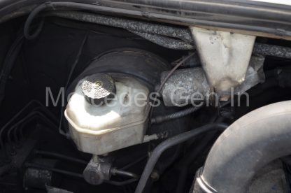
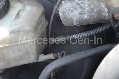
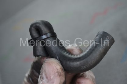
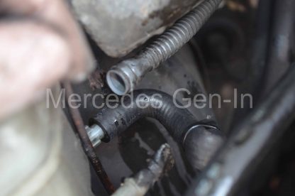
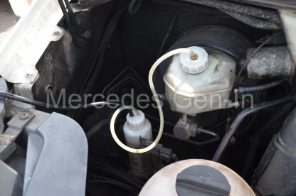
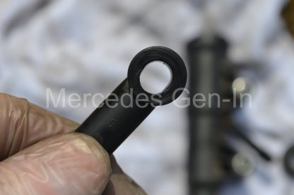
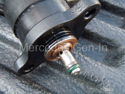
The fuel rail must provide an absolute minimum cranking pressure of between 250 and 300 Bar, any less and the ECU will not allow the engine to start. Causes for this pressure not to be maintained could be due to internally leaking injectors, faulty fuel pressure regulator or its O-ring seal (see covering article here), faulty rail pressure sensor, High or Low pressure fuel delivery pumps. Equally any air resident in the fuel delivery system will hamper starting. Usually the seals used to terminate the clear plastic pipes from the low pressure to high pressure pump give rise to air bubbles visible in these pipes, which is not a good sign and will need to be further investigated. It is worth noting that unlike any circulating diesel feed system, the fuel exiting the high pressure pump is not self bleeding and any air held within the rail will take some time to clear should you open the system to atmosphere (for instance if you do a poor job of pre-filling a new fuel filter at service).

Sprinter >2006 Cutting out and None Start 1

It is worthy of note that the diesel pressures within the system of a running engine could be in excess of 1,600 Bar that is very capable of doing you some damage! – always use caution when inspecting and working on running CDI fuel systems.

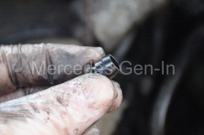
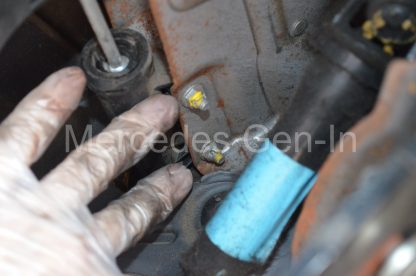
Should at any point the measured pressure drop within the fuel rail, say if there were a serious ‘high-side’ leak or if you were to open a feed union to an injector the ECU would instantly cut the fuel delivery and shut down the engine as protection. Equally there is overpressure protection for the fuel system, where if it ever rises beyond a predetermined ‘safe limit’ the ECU operates the shut off valve on one of the three piston element heads of the HP diesel pump thus dramatically reducing delivered pressure to a safe level. This shut off device is the large tower like solenoid that extends from one element (there are three) of the high pressure pump, it has a two pin electrical connection and loom plug at its end.

Sprinter >2006 Cutting out and None Start 2

‘Live data’ is the best way of determining fuel system pressures and the operation of the engines attached control devices, but obviously in a running engine. You will have to inspect the fuel system of a dead non-start engine using the functional details above as a guide. Unless you have a major fuel leak or the delivery pumps have catastrophically failed, fuel related problems are not often sudden and tend to show themselves as intermittent transient problems for a period of time before they get to the stage where the vehicle will no longer start. More often non-start problems arise from the electrical system.

A really useful link on the Sprinter fuel injection system here

Electrical

For the most part the electrical system will be the major cause of any none or poor starting issue. There are two main timing sensors fitted to the engine: Crank Position Sensor and Camshaft Position Sensor.  These relay engine positional information to the ECU so that it can determine when to accurately fire the injectors so that the engine can run.  Any synchronisation errors that occur between these two primary angle measuring devices will cause an engine to slip into limp home if running, and if stopped, the engine will not restart until it gets valid signals from both.  The cam position sensor is mounted on the top rear of the valve cover slightly to the left of cylinder 4 (rearmost looking in) and gets its positional signal from a lobe on the cam. Due to its location directly above the exhaust manifold, it is subjected to regular extremes of heat and daily cycles of hot and cold.  It is not uncommon for this sensor to exhibit thermal problems, where a cold engine will start and run fine, then once warm, would falter or not restart until cool. Replacement of this sensor is quite cheap – sub £30, and even if it does not cure any problems you may have, it is best to ‘eliminate it from enquiries’ if there are any synchronisation errors recorded.

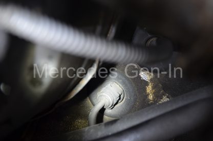
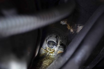
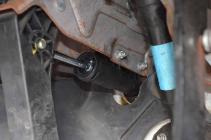
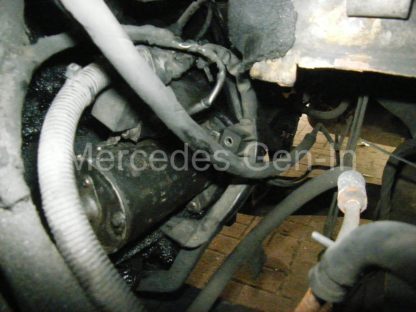
The crank sensor lives on the block seam of the engine and gearbox bell housing, just above the starter motor, it picks up its pulses from teeth on the flywheel. Generally it is quite reliable – if you have problems starting the vehicle it is often a good quick check to watch the tacho needle flick slightly as you crank the engine. If it flicks, then this is normally a sign of an impulse from the sensor reaching the ECU. If however the tacho needle does not flick on spinning the engine over, then suspect crank position sensor problems.  It is possible this sensor can suffer from thermal problems but not as frequently seen as with the cam sensor.

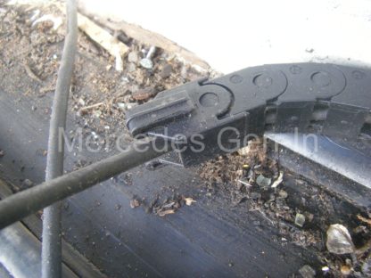
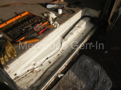
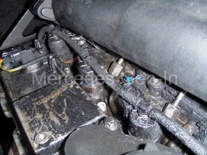
The connecors and cabling to the injectors are important things to check, if any connector to any single injector becomes disconnected, then the engine will not run, equally if one injector solenoid becomes disconnected when the engine is running the engine will die.  It is a known problem for the injector wiring loom that lies under the black plastic cable tray beneath the fuel rail to have issues whereby the injector cables rub and abrade against the metal surface of the alloy rocker cover over time. Once the cable insulation weakens and any of the conductors short to ground, it has a similar effect to disconnecting an injector – the engine will stop. You can cut strips of plastic bottle and slide them under the cable tray to insulate the cable from the alloy cover to test if you suspect this is an issue.

Sprinter >2006 Cutting out and None Start 3

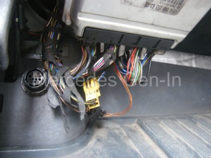
The injector solenoid wiring can be easily checked for continuity and insulation to ground by removing the injector connectors and metering out the wires directly to the ECU under the dash.  The injectors connections are the large gauge wires on the push in connector to the far right looking at the ECU under the dash.  Release the ECU retaining springs to drop it down into the passenger footwell to make it easier to work on.

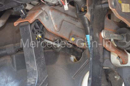
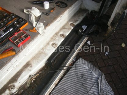
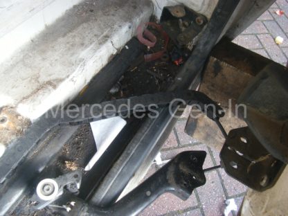
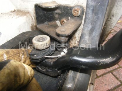
If you detect anything untoward with the wiring during your continuity checks, the first obviously place to look for broken cables and damage is to cut open the outer insulation on the section of loom that drops from the engine, over the left engine mount on its way to the rear of the battery shelf area. Here you will find the most mechanically vulnerable selection of sensor and engine management cables – be sure to check here first. Note: although not related directly to non starting, as previously mentioned in other posts, the turbo control, vacuum solenoid valve loom, hooks round the front of the radiator from behind the passenger headlamp and travels across the front crossmember. It passes the horn onward to the vac valve situated under the air box. Commonly this loom is found to be damaged or broken in the area where it snakes past the headlamp tinwork on the front panel. See here for more related fault finding detail.

If all fuses prove good, and the engine cranks but will not fire, then take a look at the ECU connectors. Remove each of the plugs and check that water, usually from a poor windscreen seal or rust-rotten screen surround, finds its way onto the ECU.  Over time the fine connectors and pins start to corrode and all manner or electrical issues ensue.  To remove the ECU plugs with lever tabs, push in the small locking pip just behind the upright grey lever, on the black part of the shell. Then bring the grey lever down over it and continue to move the lever to the horizontal in an arc, this will eject the connector from the multiplug.

Sprinter >2006 Cutting out and None Start 4

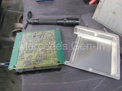
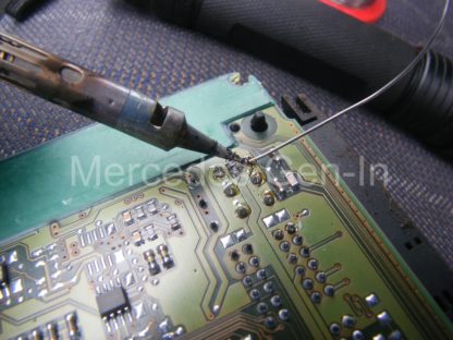
I have had instances where intermittent cutting out has been due to dry joints on the PCB inside the ECU alloy box.  To check this out – once all the cables have been removed undo the six torx head screws holding the cover plate onto the pressed aluminium ECU box. Once removed, lift off the plate and remove the PCB assembly from the pressed case.  You can now inspect each pin solder joint with a magnifying glass to look for a broken or poorly soldered/corroded joints.  Often careful re-soldering of the suspect joint will provide a suitable repair, obviously if its corroded rather badly, the chances are that the multilayer board is damaged and at worst a replacement ECU could be needed (very rare).

Sprinter >2006 Cutting out and None Start 5

If you ever get any code reader messages relating to ‘capacitor voltage low’ (Autel or none-Star diagnostic tools) I have always found these to be a good indication of faults connected to the CPS, and after replacement or repair to its connecting wiring, it has always fixed the problem which was originally accompanied by an engine that will just cease running for no apparent reason. My first advice would be when the only recovered code is one relating to ‘capacitor low’ then more often than not – its related to the CPS and well worth a try first!

Sprinter >2006 Cutting out and None Start 6

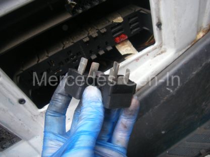
Notice the relay on the right has a ‘pushed-in’ terminal

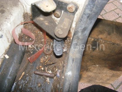
If the starter does not crank at all, then it is good to understand that the start command is issued by the ECU and not the key!  This is because the ECU monitors the key security module and will disallow starting unless a valid key (with correct internal chip) is being used in the ignition switch.  Any problem that displays ‘KEY ERROR’ in the dash LCD module is connected to using an incorrect key, a broken or missing key code chip, or a problem with the key reader detection coil (around the ignition switch) or the key security module itself (SKREEM).  If the key signal is valid the start signal will be actioned by the ECU. In auto versions it will also look to see if the transmission is in neutral or park.  Once an ECU start output is active, the start relay is commanded.  It lives beneath the driver seat, accessed through the flip off side panel, once caused to pull in – this puts voltage onto the coil of the starter motor, via a black with yellow tracer wire in the loom.

Sprinter >2006 Cutting out and None Start 7

more clearly – the pushed in relay contact

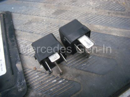
I have seen odd instances where because of the nature of the size of the relay spades, they ‘give-way’ when pushed into the fuse board receptacle, pushing them up inside the relay case – misaligning the internal switch contact faces. Often a root cause of intermittent starting/cranking with just a ‘click’ – should obviously the battery and starter cabling prove to be in good order.  The dead giveaway here is if the headlamps stay bright and hardly dip when an attempt to crank is made, if it is not the relay and good voltage is reaching the stud terminal on the starter solenoid, then the chances are the solenoid itself is faulty and the starter would need replacement.

Sprinter >2006 Cutting out and None Start 8

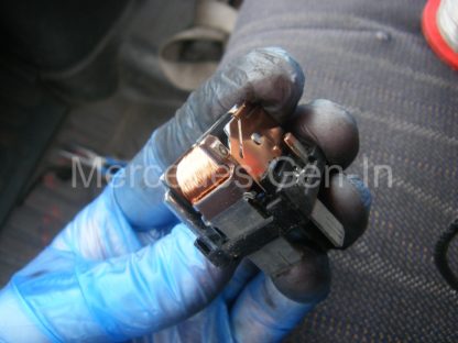
Inside the relay – the silver plated contacts are pushed out of alignment making for poor or high resistance switching

You can of course quickly test the starter by ensuring the vehicle is out of gear and then shorting the large 13mm power stud/nut on the starter to the smaller 10mm nut on the solenoid with a robust old spanner or jump lead clip. If the starter is healthy, then the motor should crank. If not, then you are most probably looking at a faulty starter motor.  If it does crank, and will not turn over from the key, then you will have to investigate why following the information in the above text.

Sprinter >2006 Cutting out and None Start 9

I hope the above gives you a little information to help you fault find a few little known anomalies with the Sprinter and hopefully it leads to identifying  your starting issues.


Late model Sprinter / VW Crafter Front Wheel Bearing Hub Replacement


A noise that was unmistakably a wheel bearing in its last throws of life had grumbled away for a number of weeks before eventually becoming too loud for the driver to ignore and the van was bought in for attention. Once the front end was lifted it was easy to hear which side was the issue, simply by spinning the wheel a little and listening for the dry rumble of a worn bearing. On this occasion it was the offside or drivers side that required replacement.

Sprinter Crafter Hub Bearing Assembly - This would have to be removed and pressed into the cast hub carrier - Quite a job without serious tooling!

Hub Bearing Assembly – This would have to be removed and pressed into the cast hub carrier – Quite a job without access to some serious tooling!

The demands of the transport business dictate how this job is attacked in many ways. Speed of turnaround and the economy of ‘time off road’ are the most important factors and this job is one that if done in the manner described can be completed in under two hours – if you consider any other way, unless you have access to some serious pressing or tooling and a few unexpected new parts along the way, then the long-hand method is best avoided – believe me!

Used complete hubs are plentiful as they are interchangeable between Sprinter and Crafter models so its pretty much ‘anything will do’ as long as it is the correct side. You can pick up a used item with fitted ABS sensor (necessary as 99 percent of the time they will break on attempted removal!) for around £60 – £70 often cheaper, once you have located your spare part you are all set to sprint to the finish. The main issue in removing your own hub and pressing in a new £40 bearing is the difficulties and special press required. If you have to buy in the engineering expertise to press out and fit the new item for you, you can add another £30 cash tip to the job, plus your waiting time for them to do the job.. so the cost to keep you running is about the same – albeit with a used complete hub assembly and not new part. Add to that the possibility of the engineering shop breaking the ABS sensor, which would cost you another £40 plus to replace. Enuff said!

Sprinter-Crafter-906 Hub

Used replacement complete hub assemblies such as this one are plentiful and quite cheap to source for example from user vansevicesltd on EBay

So you have located your chosen spare part and are ready to install. Loosen the road wheel and jack the vehicle under the chassis subframe section that supports the wishbone eye bushes, get as far to the wishbone pivot line as possible as some of the steelwork that exists in that area, especially the U channel that runs beneath the engine, left to right, is only of light gauge and will collapse/bend on any attempt to support any weight on it.

Once the vehicle is in the air, remove the road wheel and wire brush the lower hub balljoint nut, steering track rod end nut and the two connecting strut/damper to hub bolts. Be sure to include all exposed threads, the cleaner they are the easier to remove. Spray penetrant and allow to soak.

Using a 30mm Hex socket and breaker bar undo the lower balljoint nut and run it off to just over the exposed threaded section. Use suitable packing beneath the joint to the ground with a short axle stand or wooden blocks and carefully lower the jack so a reasonable amount of vehicle weight is supported on the joint. Taking a heavy engineers hammer whack the casting to the front lower edge of the hub near where the taper of the balljoint is located, be sure not to miss and damage the boot gaiter or anything else that happens to be around. Usually two or three good blows will part the joint and once this is achieved, jack up the vehicle again to support its weight from the chassis.

OLYMPUS DIGITAL CAMERA

VW Crafter

Use a 21mm Hex socket and breaker to undo and remove the steering ball joint nut, either use a lever type ball joint separator or the hammer method above to release that ball joint too. Undo the torx head recessed fixing that secures the brake disc to the rotating hub. Swivel the hub to gain access to the two caliper hanger to hub bolts. 21mm again and breaker will loosen these off, be sure to lever back the pads a little in the caliper to enable easy removal of the assembly off the brake disc. Removing the two hanger bolts completely, use wire to support the caliper assembly under the wheel arch out of the work area so that the brake hose does not get pulled or strained. Tap off the brake disc from the hub centre and place out of the way.

Ensure the ignition is off and key out before proceeding as any ABS sensor removal while ‘ignition-on’ could result in a fault code being set, possibly requiring clearing from the ECU. Best avoided if possible (extra time and money).

Using a 10mm socket remove the plastic nut just forward of the roll bar on the plastic arch liner, lever this out slightly and trace back the ABS sensor wire and unplug it from the connector block hidden behind. ABS is usually the lower of the two connectors, the upper one is the brake pad warning sensor wire.

Using a 21mm spanner to back the bolt heads, use the 21mm socket and breaker bar to loosen the two strut mounting bolts. Note at this point that the top bolt is a slot and the bottom bolt is a hole. This is to allow adjustment of camber angle of the road wheel and should be returned to its original position as much as possible. Normally the bolt head position is easy to relocate on the strut leg as it has left a clean area where it has sat, simply make sure you refit this top bolt to position on assembly. Drive out the two strut bolts while supporting the hub, once free, lower off the lower balljoint taper. The hub is removed!

Replacement is exactly the reversal of removal with the proviso that once completed you pump back the brake pistons from the brake pedal so there are no disasters on first road test.

This hub swap should only take in the order of an hour and a half to two hours to complete, which considering the perceived scale and enormity of the job is pretty good going and this procedure is very possible for the home mechanic to undertake and acomplish without little problem.

Mercedes-Benz Sprinter

Mercedes-Benz Sprinter