Technical S Class W220

Mercedes S500 (W220) and others – ‘Fly-by-wire’ throttle pedal fault


There had been occasion when I would decelerate to an intersection or junction and the engine would not settle to an even idle and remain rather ‘lumpy’. By tapping the pedal only slightly to raise the RPM’s by only the smallest amount resulted in the engine dropping back to its normal smooth idle.  It was also noticed that when pulling away from a junction the accelerator pedal occasion required more travel to get the car moving than it normally would, and when it did begin to pick up speed it moved perhaps more swiftly than intended.  There were no reported engine codes and also nothing illuminated on the dash to indicate a problem.

Asking around, a faulty throttle pedal position sensor was the confirmed as the most likely cause and the consensus of opinion was that they rarely ever caused a fault code to be registered, in fact one of my best contacts in the trade said that this condition directly pointed to the pedal issue, doubly confirmed by the fact that no code was reported.

Mercedes Electronic Throttle Pedal Problem 1

So I purchased a used part from a local breaker for £35 and fitted it in less than quarter of an hour from start to finish.

All that is involved is to remove the floor mats if fitted to gain unhindered access to the accelerator pedal.  In the rear moulding there is a plastic circular bung about half way up the assembly, using a small screwdriver or pick lever this out.  Beneath lies a recessed 10mm nut and washer, undo this with a small socket and extension.  Now grasp the pedal and lift it upward from the bottom, levering it outwards slightly to clear the fixing stud, once clear, pull down to disconnect the pedal assembly from its top locator.  The pedal will now be free, retained only by two wiring/loom connectors.

Disconnect the upper multiway plug to the position sensor model and remove the smaller two pin connector from the ‘kick-down’ switch from behind the pedal.  Note how the kick-down wire is threaded along the side of the pedal assembly and remove it.  The pedal can now be replaced with the new unit, threading the thinner loom back in its correct position and then connecting both wiring connectors back onto their respective plugs.

Feed in the pedal assembly, upper section first. Once located correctly, swing down the pedal to mate with the fixed mounting stud and replace the fixing.  Job done, all you then need to do is replace your mats and test the vehicle.

Mercedes Electronic Throttle Pedal Problem 2

On the S500 (W220) there were two types of pedal assembly used, one with a part number A220 300 01 04 for the post face-lift version circa 2004 onward and  part number A220 300 00 40 for the earlier model ranges to this point. Its a good idea to remove your own pedal, as it is such a simple task, to check the part number of the item fitted before searching for a spare.  A new non Mercedes replacement should cost in the order of £150.00 and a genuine part closer to double that.  A good used item should be in the range £35-£70 – the choice is yours!

Throttle pedal fault Mercedes Benz 1

Interestingly there is a large number of people who still believe there is a potentiometer within the pedal assembly, this is of course not the case and the often read advice to spray switch cleaner on or around the sensor is largely futile.  I have taken (broken) this unit apart so that you can see inside and confirm that in this case and most of the Mercedes models from about year 2000 on, this pedal assembly is all solid state and non serviceable.

Throttle pedal fault Mercedes Benz 2 Throttle pedal fault Mercedes Benz 3

What you can see within the housing is a pair of hall effect semiconductors mounted to a PCB. Each sensor is fixed within a static soft iron slotted core and as the pedal is rotated a small annular magnet rotates about this core.  Minute changes in magnetic field are detected by each of these two ‘Hall Effect’ sensors (compared electrical outputs from both sensors are checked for integrity, before a plausible position signal is accepted by the ECU as a failsafe, much in the same way as there is mechanical failsafe protection built into the pedal assembly by having two individual springs controlling the pedal return, just in case one breaks, allowing the pedal to return to a safe ‘throttle closed’ position rather than simply falling to the floor in a ‘full on’ scenario – Which would be a grand ‘brown trouser’ moment.)

Throttle pedal fault Mercedes Benz 4

Each degree of throttle pedal rotation at the rotating hinge point, relates to a predetermined magnetic field strength and this is interpreted as positional data referenced back to the ECU.

Throttle pedal fault Mercedes Benz 6

So, not a carbon track of a potentiometer to break or wear out, just electronics.  Obviously failures occur but in general this is a far more reliable, if slightly more complex solution to throttle pedal position sensing.  I would imagine the most common problem with failure of these pedal assemblies is the ageing of the semiconductor devices, once one device gives a slightly different output at any stage of its sweep, this is interpreted by the ECU as a mismatched signal and it will be ignored – hence dead pedal!  Once the signals are again in unison the throttle position is relayed and off you go…

Skipping Mercedes 6 Disc CD Changer – Work-around Fix


The older type of CD Changers fitted to vehicles that are ten to fifteen years young, if still in situ, are running on borrowed time. Complex electromechanical systems and solid state LASERs don’t have an infinite life and often replacing the unit with a more modern radio/cd or MP3 player is the best choice.  However for those of us with older integrated COMAND systems that use a dedicated cut out in the dash, it is not always practical to change the head unit to a more modern type without huge expense and if we want to play CDs the remote changer has to work as the slot up front is for the NAV disc only.

Mercedes Benz CD Changer Repair Work-around 8

So what do we do then…  The option is to source a used unit from a scrap car or breaker but it is most probably from the same era and will most likely be well on its way to end of life.  So if you have an issue of ‘Magazine Empty’ or a badly skipping CD changer then there is a couple of last things to try before lifting the lid on the recycling bin and dropping it in!

As the LASER ages it becomes less powerful, rather like a halogen bulb that yellows and gives off a degraded level of illumination to that it did when new.  What we can do is increase the current to the laser slightly to lift its light output to compensate for its ageing and hopefully put the player back into service for a while longer. (please note that by increasing the LASER current over the specified factory set optimum, will have the effect of shortening its life, but my view is – if the player does not work correctly now because of a poorly performing aged LASER reader, then it clearly can only really be fixed by replacing it – a cost option that usually outweighs the purchase of a complete replacement player.)

Mercedes Benz CD Changer Repair Work-around 7

Obviously it goes without saying that it may just be dirt that is hampering the function of the CD player and in a few cases cleaning of the LASER lens will rectify the problem. This is the thing to try first before making any electrical adjustment. You can use one of the specialist cleaning CDs you can buy with a fine brush attached to the playing surface.  As this is drawn into the disc changer and played, the fine brushes gently sweep dirt and dust particles from the lens at very high speed.  More stubborn dirt will have to be removed with the delicate use of a cotton bud and surgical alcohol.

Mercedes Benz CD Changer Repair Work-around 6

Assuming that you wish to proceed with trying to breathe a new lease of life into your old disc changer, and that you are not too bothered by the chance of failure – then read on.

Eject the CD cartridge from the mechanism, disconnect the cables and orange DB2 fibre connection removing the player from its bracket in the car.  Working on a table or bench, unscrew the four cross-head screws from the sides and three from the back of the unit case, two of these hold the fibre convertor.  This then slots off sideways and the orange ribbon can be disconnected from the PCB connector by simply sliding out the white plastic anchor section about 2mm, releasing the foil from the PCB.  Now completely lift off the cover.

Mercedes Benz CD Changer Repair Work-around 5

Unhook the spring loading mechanism from each side of the unit, noting the position of the levers before doing so. These are set depending on your player installation – either Horizontal or Vertical.  Now pull off the four ‘gel’ shock dampers from the retaining spikes on the inner chassis (2 on each side) and undo a single retaining philips screw on the connecting orange foil assembly.  The inner chassis should now pull free from the base section.

Mercedes Benz CD Changer Repair Work-around 3

Identify the laser saddle and turn the lead-screw cogs with your finger to drive the LASER to the outer edge of the chassis, once in position turn over the player and you should be able to see the floating lens assembly through a gap in the mechanism top plate, there is enough room here to slide in a cotton bud and lightly brush the lens clean.  Use alcohol if any deposits are stubborn or difficult to remove, dry thoroughly and polish off any residue lightly with a dry cotton bud.  You may wish to try the player to gauge any improvement at this point, before moving on to the ‘last stand’ of adjusting the LASER current to get that last bit of life out of the player.

Mercedes Benz CD Changer Repair Work-around 2

Go back to the lead-screw and run the LASER to its most inward position in the chassis and then look on the revealed vertical edge of the saddle and you should see a small ceramic trimmer or potentiometer, about 3 mm in diameter.  This adjusts the LASER current. On Older wired and DB2 Mercedes and BMW, Alpine and Becker changers – current is increased by rotating this tiny trimmer anti-clockwise.  It only needs to be moved by a small amount, as a small increment is often all that is needed to restore the player to a working state that may last for a good period of time, maybe year or even more depending on your luck!  Remember the LASER is probably problematic anyway due to its age, so by increasing the current you are stressing it beyond its designed limits – but if you win a year or more use out of it before the inevitable replacement of the changer – whats to lose!  Rotate the trimmer about 30 degrees anticlockwise and rebuild the unit and test.  More often than not this is all that is needed to get things running again.

Mercedes Benz CD Changer Repair Work-around 1

If you need to apply power to the CD changer while on the bench, dismantle the fibre converter housing and attach 12v DC supply as shown across the power diode on the PCB

Good luck! Remember this is not a repair, it is hopefully a ‘get-out-of-jail card’ used to squeeze the possibility of a little more operating time from a unit that is eventually going to fail.  Usual disclaimers apply, you do this modification totally at your own risk under the full understanding that it may not work for you and that it could backfire and you end up junking your classic player.


P0410 Secondary Air Injection Fix – Mercedes S Class W220


Mercedes P0140 Secondary Air Pump Problem 1

Mercedes Benz M113 Engine S Class S500

I have recently taken delivery of a used S Class Mercedes, 2002 model W220.  During the first few days of ownership the amber engine check lamp in the dash illuminated and stayed on. Plugging in the AUTEL diagnostics tool revealed a P0410 fault code relating to secondary air injection, so I set about troubleshooting and fixing the problem.

Mercedes P0140 Secondary Air Pump Problem 2

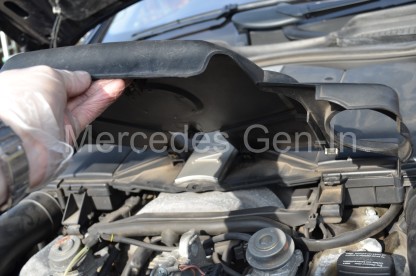
Remove front section of engine cover by lifting up and pulling forward.

Apart from aiding to prolonging the life of the catalysts and meeting lower emissions  targets the secondary air circuit does not effect the normal running of the vehicle if it is disabled in a particular way until a fix can be carried out.  You may remember older engines such as the 320 I6 of the R129 ran at elevated rpm’s until warm and held on to auto gear changes until the CATs were up to temperature – this is an alternate design.

Mercedes P0140 Secondary Air Pump Problem 3

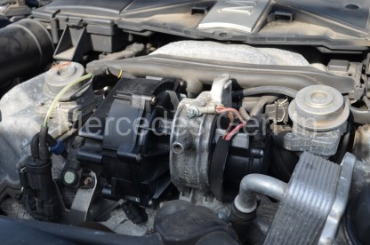
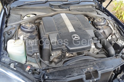
Air pump mounted between the ‘V’ of the cylinder heads at the front of the M113 engine

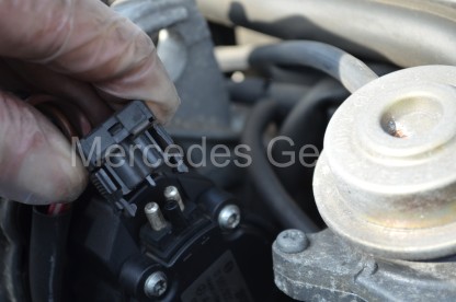
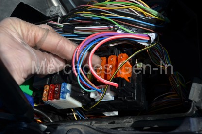
The way to disable the system is to remove and plug the single vacuum outlet (the base of the clear thin pipe to the left in the picture above) from the control solenoid to the air check valves, one either side of the v6,v8 and v12 variants, then simply pull the control relay from the right hand fuse board in the engine compartment. Relay N. or pull fuse 31 (40A) orange.  This will accomplish two things until you get chance to repair the system, although please note it will not extinguish the engine check lamp. It will prevent any electrical current flowing to the secondary air pump and it will also prevent the air check valves on the exhaust manifolds opening with the possibility of allowing exhaust gasses to exit via the disabled air pumps delivery pipe.

Mercedes P0140 Secondary Air Pump Problem 4

People have wrongly assumed that the secondary air system only operates at start up, this is not strictly true.  What happens at a variable point during the drive cycle when certain engine conditions and running criteria are met, is that the secondary air pump is cycled for a short burst, check valves are opened and the ECM monitors and compensates for a change in the O2 levels measured in the exhaust gasses.  Here is some info on the conditions that are required to be met for a check to be made by the ECU/ECM.  It is worth noting that it takes faults to be detected on two engine start/run cycles for the engine management lamp to illuminate on the dashboard.

Mercedes P0140 Secondary Air Pump Problem 5

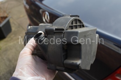
Mercedes – Secondary air injection pump.

It does this among other things by monitoring fuel trim and by identifying emissions changes then comparing its findings to an inbuilt reference map.  From this it can conclude that the secondary air circuit is functioning correctly – engine management is happy!  Should it detect a incorrectness or deviation from the changes expected within the combustion gas control loop, then it will flag up a secondary air injection error.  The reason it checks in this manner during the drive cycle is it can effectively test out all components in the circuit in a few seconds, air pump, air supply piping, electrical controls, check valves and actuating vacuum etc.  If even one of these control sections is giving issue, then its comparative live testing will result in a fail and flag the P0410 fault code.

Mercedes P0140 Secondary Air Pump Problem 6

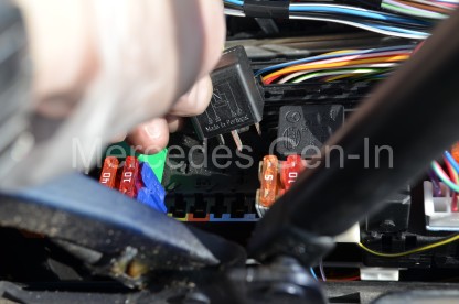
Both control relay and fuse located in right hand fuse board.

On start up from cold the secondary air pump relay ‘N’ is commanded to close, this applies voltage to the air pump DC motor protected by a 40A fuse, Fuse 31.  At the same time the electrical solenoid controlling the check valve vacuum is energised, allowing vacuum to pull open both diaphragm caps.  Air is collected and pumped into the check valve heads by the twin vane air pump into a rubber supply hose that interconnects both air check valves. Air enters the open diaphragm caps and passes through a pair of non-return ‘reed’ valves into the exhaust header or manifold on each side of the engine (In a V configuration – obviously only one check valve if this system is used on any in I4 or I6 engines)  Pumped air then mixes with the combustion gasses and achieves the engineered effect of raising CAT temperature and assisting in burning off any traces of enriched combustion fuel, cleaning up its act during the initial start cycle.   The pump/blower running time is usually between 45 and 90 seconds after which the turbine will cease to rotate, check valves will close and unassisted combustion will continue.  Only after the engine has warmed up and at some further point during the current drive cycle will the system be checked once more for correct operation.

Mercedes P0140 Secondary Air Pump Problem 7

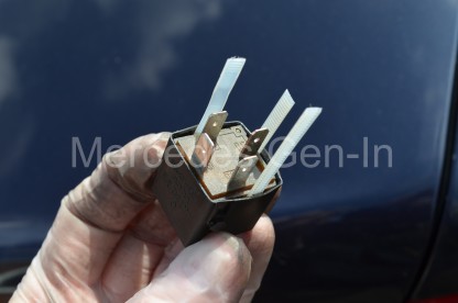
Secondary air injection control relay ‘N’ Right hand side fuse box under bonnet/hood. MB part No. A002 542 1319 Has built in coil suppressor resistor. Bosch Part number for this item cross references to: BOS 0986332040

Mercedes P0140 Secondary Air Pump Problem 8

Secondary air injection protection fuse 40A – Fuse 31- Orange Maxi-fuse

There are several faults that can occur to raise the P0410 code and resulting amber warning lamp, but often it is down to a failure of the secondary air pump itself.  What commonly happens is that the normally open TYCO power relay N ‘splashes’ its contacts and sticks closed, due in most to continued contact arcing. The relay is rated at 35/40A and the current drawn by the secondary air pump under full load can be as high as 35A which as an inductive load pushes the relay to it maximum as far as contact rating is concerned.  Once the silver contact area of the relay has deteriorated unreliable operation will result.  Worst case is that the relay sticks on and the air pump remains powered beyond its 90 second period and running continuously to its final destruction.  Relays in this circuit as well as ones in the Air-matic circuit should, in my view, be changed as a service item every 50k or so miles to attempt to prevent costly pump repairs.  A new secondary air pump from Bosch will cost in the order of £300 for the part alone and maybe £35 for the correct relay.  The resulting maths is simple.

Mercedes P0140 Secondary Air Pump Problem 9

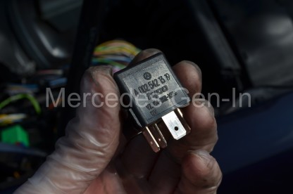
Control Relay ‘N’ MB part No. A002 542 1319

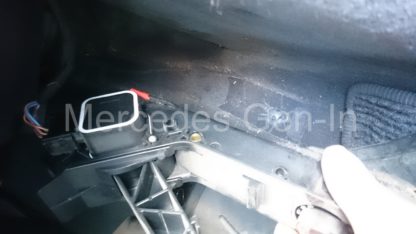
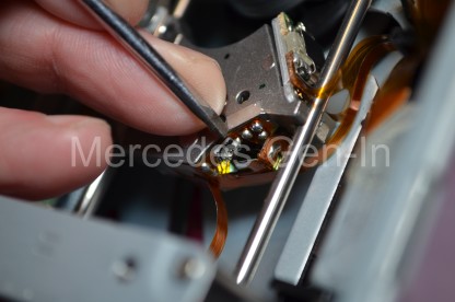
Testing the pump is straight forward, lift up and off the front section of the plastic engine cover and remove the air pump power connector, apply 12v to the exposed contacts from an external source and listen to the sound the pump makes – if any. It should sound like a vacuum cleaner motor as it spins at a very high rate, if it sounds like its arcing or rough running its probably at end of life. If you have the means of monitoring the running current of the motor (DC clamp meter) ensure it is running to spec.  Removal is done by removing the single reverse torx set screw from the aluminium saddle plate that clamps the pump between the front of two cylinder heads.  Once this forward facing saddle plate is removed, work loose the rubber connecting hose from the pump outlet and once free, remove/jiggle the pump free from the car.  Replacement is an exact reversal of this procedure.

Mercedes P0140 Secondary Air Pump Problem 10

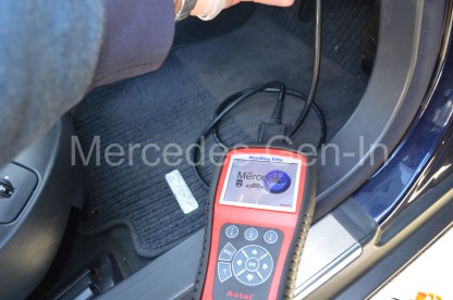
OBD port under dash area next to driver footwell.

The pump if faulty must be replaced along with the N control relay and if blown Fuse 31 (40A).  As it is most probable that the pump failed because of the relay it should be changed as a matter of course in all cases as we would not want the new item damaged in the same way as the old one – just for the sake of a new relay!

Mercedes P0140 Secondary Air Pump Problem 11

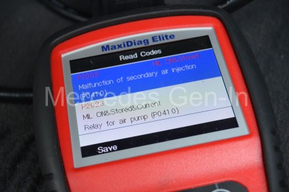
P0410 Faults recorded and cleared with Autel MaxiDiag Elite. Once erased you will need to cycle the ignition for this fault to fully clear.

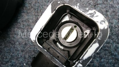
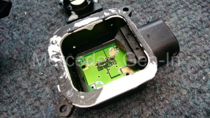
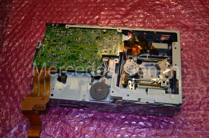
I have dismantled both the N relay and secondary air pump so that you can how the items are made up and the issues that cause the relay to stick and the motor to self destruct, there are a few additional photographs below showing the detail of this ‘post-mortem’ carried out on the damaged parts for useful info.

Mercedes P0140 Secondary Air Pump Problem 12

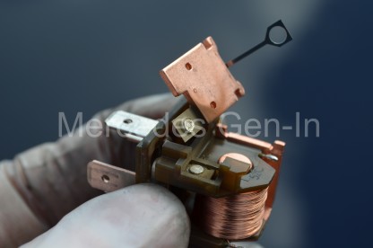
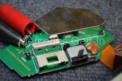
Burned contacts from relay ‘N’ that stuck closed causing the secondary air pump motor to run to destruction.

Replacing the ‘N’ relay is simple, locate it in the central portion of the right hand (drivers side UK) fuse board k40/7 module or SAM in the engine bay (right side fuse box detail here), fuse 31 is there also, and is the most inboard of the three 40A orange Maxi-fuses located toward the front edge of the SAM.

Mercedes P0140 Secondary Air Pump Problem 13

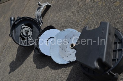
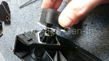
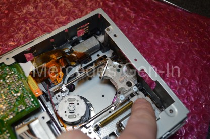
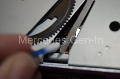
Internal parts of secondary air injection pump.

Obviously when you have completed the work you will need to erase the fault code flag from the ECU with a suitable code reader, in this instance I used my Autel. The standard OBD port is under the dash next to the drivers foot well, near the bonnet release on UK cars.

Mercedes P0140 Secondary Air Pump Problem 14

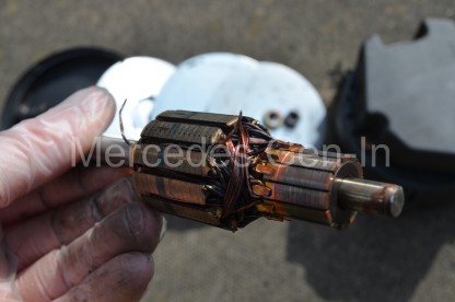
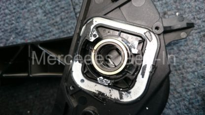
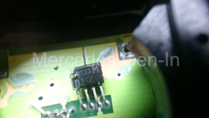
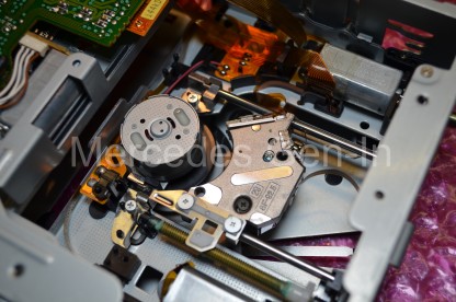
Burned out rotor of the air pump, probably due to overheating.

Once the work is completed, leave off the plastic engine cover until you have started the car from cold, you can then hear the fan running and monitor at what point it shuts down (45-90 seconds after cold start) if it continues to run much beyond this time there is likely to still be a problem somewhere and you are best to disconnect the motor until it is further investigated as it is a high power, high rpm motor that is not at all rated for extended use beyond its designed short duty cycle.

It is worth checking the vacuum actuation components and piping with the pump motor housing removed, any hoses that are split or look bad should be replaced. A word of warning – do not pull or disturb the slightly thicker flexible vacuum pipe that disappears into the central ‘crutch’ between the front of the cylinder heads, if this becomes detached/broken then the complete engine has to be stripped to reattach it.  You are best to identify this hose before working in the area – In my view it is best left undisturbed!

Mercedes P0140 Secondary Air Pump Problem 15

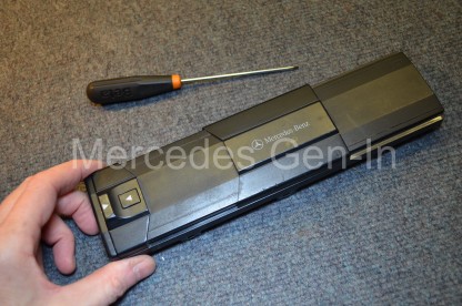
How to safely remove the case of a power relay for inspection. Pry each side carefully with a screwdriver just enough to insert a cut section of cable tie, once all four sides are like this the relay will simply slip out of the case without damage.

In the vicinity of the black vacuum solenoid that diverts supply to the air check valves is a small blue plastic vacuum check valve, these have been known to stick and cause incorrect operation of the air injection check valves.  Often in colder weather, moisture accumulates in this device rendering it intermittent in operation, as the weather warms and it dries out then the problem disappears, only to return once the weather dips back to winter humidities again.  If you can replace this part while you are in there, do so, its cheap and readily available through the dealer parts network or from several web based pattern part sources.

Mercedes P0140 Secondary Air Pump Problem 16

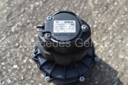
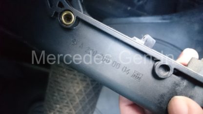
Label on the air pump showing both Mercedes and Bosch part numbers, For the S500 W220 and ML320 W163 the MB part number is: A000 140 37 85 If purchasing used parts check these two numbers against your replacement.

Once you are satisfied all is well, refit the top plastic engine cover, check the fuse box lids are locked closed and clear any leaves or debris from the bulk head drain holes/flaps before shutting the bonnet and congratulating yourself on a job well done!  A job that would have cost in the region of £1000 with not much change, if it were to have been done at a Mercedes dealer.

Mercedes P0140 Secondary Air Pump Problem 17

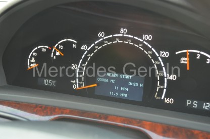
Test cold start, listen for the pump to run and switch off anywhere between 45 and 90 seconds after start. Note – fault light cleared in this picture.

As of the 12th of March 2016 I have stock of a full set of tested used parts available (Air Pump, Relay and 40A fuse) available as a ‘kit’ to carry out this repair following the above instructions – contact me for more detail and purchase information if required  steve@mercedes.gen.in