Author: Steve Ball

Mercedes Sprinter Clutch Replacement (T1N, NCV3, VW Crafter and other MB)


Clutch replacement on any vehicle can be an expensive job, especially if you are entrusting the job to a main dealer.  Although large scale and a little mauling, clutch replacement on Mercedes models can be well within the capability of a competent DIY’er with only a limited number of tools.  In this post we shall look at the replacement of the clutch mechanism (including Dual Mass Flywheel DMF) on the Mercedes Sprinter – both older and newer models.

Mercedes Sprinter / Crafter Clutch replacement

There are several important details often overlooked about the Self Adjusting Clutch mechanism or SAC, that the installer has to be aware of so that things go smoothly.  You will no doubt have read many horror stories on the web of people installing SAC clutch units only to find that on re-assembly they have no functioning clutch, then having to take it all apart again to do it properly!  The first thing to understand is how the clutch actually self-adjusts over its life and in this understanding it will allow you to assemble things in the correct manner, so when you put that last bolt in place you are certain things will work as they were designed.  If you are fitting used components, such as a second hand DMF (flywheel) or even a complete used clutch, this knowledge is ever more important.  You would also additionally need to know how check this if you were stripping and replacing the original clutch and flywheel from an engine only to replace it later, say if you were replacing a leaking rear crank shaft seal for instance.

You will remember from days of old that clutches on older vehicles used to have a different bite point as they aged, either right at the bottom or top of stroke depending on design.  This is not the case today with advancements in clutch technology.  Mercedes clutches and other vehicles too, now have circular adjusting mechanisms built into the cover plate and spring that move to compensate as the clutch wears, maintaining the release spring pressure and finger position.  This means that as a SAC clutch ages, it maintains the same spring operating position and ensures a constant actuating force to engage/disengage the clutch over its life.  Indeed it is almost impossible to tell if a modern clutch is ‘new’ or only ‘weeks from failing’ by the pedal position and feel alone – all thanks to the SAC.

When you purchase a new clutch kit you will almost always find that the clutch has been ‘set’, and is ready for installation. However it is always best to check that things are correct before fitting as I have known due to rough handling even new cover plates ‘spring’ into a full adjustment position – clearly fitting this as-is would result most probably in a non functioning clutch.

Mercedes SAC Clutch

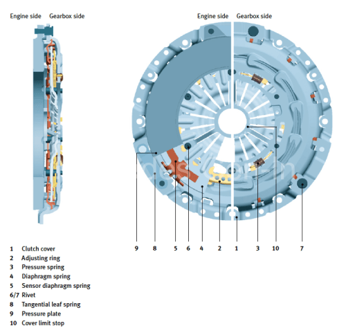
From the illustration above you will see the cover plate/spring assembly has an adjustment ring. (2)  Simply put, this circular ring is allowed to rotate if required a few degrees when the diaphragm spring is fully compressed (when the clutch is operated) Its rotational resting position is controlled by the combined action of a sensor diaphragm spring (5) and the main diaphragm spring (4), allowing the plate to slide round slightly, facilitating changing the pivot point of the main clutch springs as the driven plate wears. There are three small springs that pre-load the adjusting ring so that as the clutch wears the adjustment ring is forced to rotate slightly to drive what is in effect a ‘wedge’ into the forming clearances of the cover plate diaphragm spring at its pivot point, thus allowing clearances to be ‘auto adjusted’ within the installed cover plate.  More information about the SAC from LUK if you wish to view here.

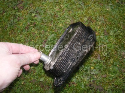
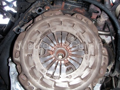
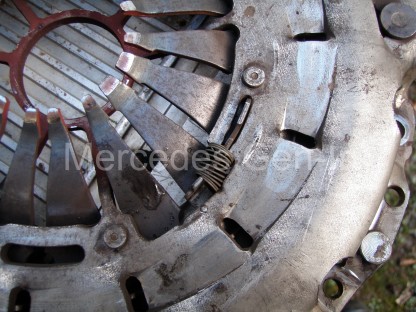
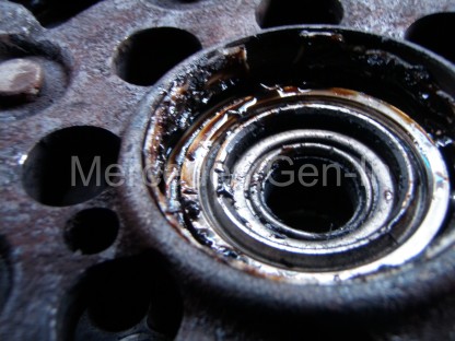
The adjustment ring’s spring position can be seen to be fully extended on this worn clutch cover plate below, the photograph below that shows the adjustment ring in ‘set’ position, this is how the clutch needs to look before fitment. Always check this before installing the cover plate, even if just out of the box!  There are many expensive tools used for correctly setting the adjustment of the pressure plate once installed on the vehicle, whilst these are great to own, unless you fit clutches every day it is hard to justify their purchase, this post outlines how it is possible to carry out this work without the special setting tools.

SAC cover plate showing adjustment ring spring positions for a worn clutch

Mercedes clutch SAC adjustment ring spring set position

If you are using a used clutch, or simply refitting your original plate, it is important to check or reset the adjustment ring to the ‘set’ position shown in the photograph directly above. This can be achieved in a press used between the stamped steel cover plate edges and the diaphragm springs.  If you do not have access to a means of compressing the diaphragm springs so that the adjustment ring can be counter rotated and reset, you may wish to read on, but use great care – as there is a fantastic amount of pressure behind those diaphragm spring fingers and a truly huge amount of force is needed to compress them!  The following is an emergency measure, only to be used to get you out of trouble and is definitely not by any means a recommendation.

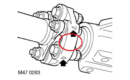
On a solid driveway, place a hydraulic trolley jack under the rear axle of the vehicle and raise it enough to fit the cover plate, supported on three stout short wooden blocks of the same size, resting on the flange/outer lips of the stamped steel plate only, NOT the pressure plate (form the wooden blocks into a triangular formation).  Using a very large socket that will generously cover the hole in the centre of the diaphragm springs, align this with the axle beam or lower shock absorber mount – use solid wood packing as needed.  When in position bring down the jack ‘very slowly’ to allow the axle weight of the vehicle in controlled contact with the socket via the wooden packing, depressing fully the diaphragm spring, almost to the cover limit stop. (shown in cut away diagram above)  Now carefully rotate the adjustment ring anticlockwise with a stout screwdriver until it rests fully against its stop and the three small springs are fully compressed.  Once achieved, jack the vehicle once more and remove the cover plate that is now set for installation.  Throughout this procedure please consider your own safety at each step of the way!

2005 Sprinter T1N Gearbox Removal

Now you can begin to remove the gearbox and fit your clutch.

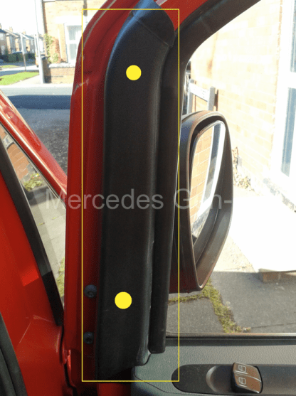
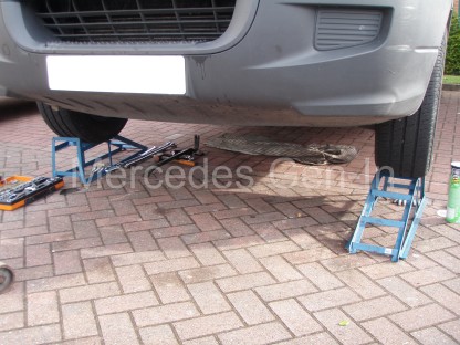
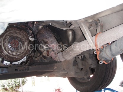
Working from ramps with additional additional 4-6 inch raising blocks if you have them, is the best way to achieve enough space to work comfortably around the gearbox, leaving yourself enough room to manoeuvre freely and eventually remove the gearbox from beneath the vehicle.  I always jack the vehicle onto ramps, this allows you to place one ramp forward and the other facing rearward, thus locking the vehicle from rolling either way to supplement the handbrake and rear wheel chocks.

Disconnect the battery before starting any work, as you will no doubt disturb the starter motor during the job. Also on later Sprinters,  W639 Vito and VW Crafter models remove the complete air box from under the bonnet, this prevents any strain on the plastic components, as the engine naturally tilts backwards when the gearbox support is removed.

Sprinter hoses and gear cables held out of the way

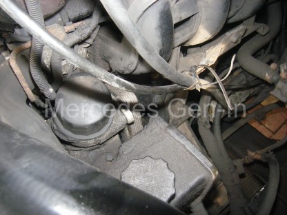
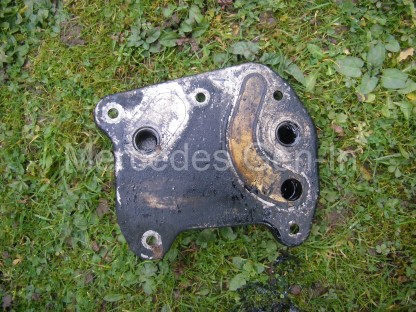
Use a trolley jack to support the plate that supports the back of the gearbox near the output flange.  Undo all the bolts that hold the support plate to the chassis rails on either side, allow the jack to be lowered and removed. This will drop  the rear edge of the gearbox down a little so that the rear gearbox mounting pin can be removed and the support plate taken out from beneath the vehicle.

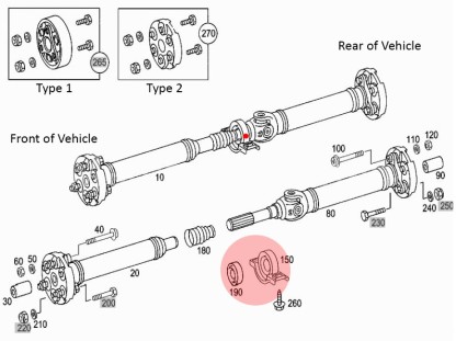
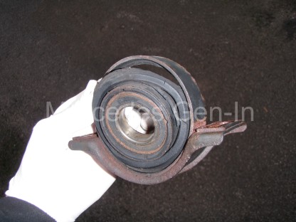
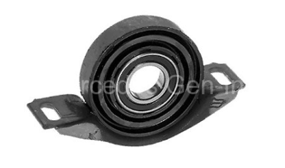
Using a 16mm socket remove the four propshaft flange bolts from the gearbox output shaft.  You will now have to remove the drop protection ‘horse-shoe’ brackets and the two centre bearing bolts to allow you to drop the prop sufficiently to allow you enough flex for it to be moved out of the working area to one side of the vehicle.

Sprinter with DMF removed

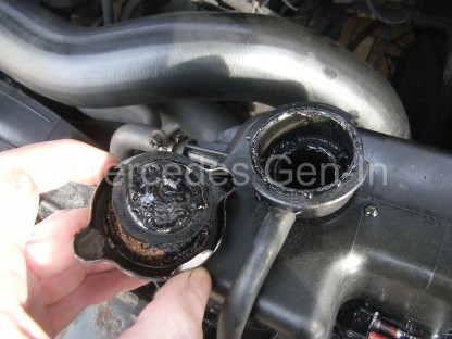
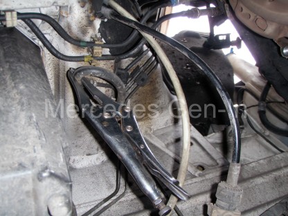
Now remove the gear selector cables, make sure you mark the shaft positions in the plastic ball-ends (amount of insertion) before you release them and tie them to one side. Put a latex glove under the cap of the brake/clutch shared master cylinder, before clamping off the flexible clutch hose from the chassis to gearbox. With a small screwdriver or pick, detach the hydraulic connection retainer clip from the gearbox hose coupling, keeping this in a safe place.  Pull out the hose and again tie it out of the way of the working area.  Remove any electrical connector or plug and tuck them out of harms way.

Now using at least a 24 inch extension bar and reverse torx socket remove all the ring bolts from the bell housing. There is no need to fully remove the starter motor, just let it rest in position.  It will be held in place by its thick cable. On T1N models up to 06, you will have to remove the exhaust support (2 x 12mm nuts) as this sits sandwiched directly behind the gearbox and will prevent removal unless fully removed.

Sprinter DMF Flywheel removed

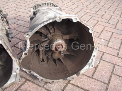
When you get to the last bell housing bolt, support the gearbox centre on the hydraulic jack, remove the final bolt. From the back of the gearbox pull, the casting should now separate from the engine block.  Manoeuvre the gearbox back and lower the jack. Take the gearbox from under the vehicle.  This is a great time to check for leaks or damage/wear to the selector mechanism. Checking the gearbox oil level is easier at this point too!

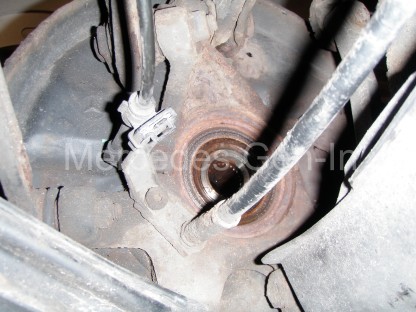
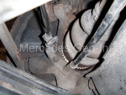
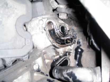
From inside the bell housing you can check the rotary smoothness of the thrust bearing, this is part of the release slave cylinder mechanism and cannot be replaced on its own. If you can afford it, always replace the slave cylinder when replacing the clutch, often if you purchase a complete kit it comes as a component part.

DMF Mercedes Sprinter Centre Bearing

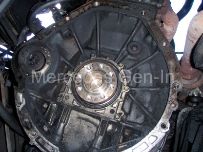
Always inspect the centre bearing in the DMF, if this is damaged it is not available as separate part from Mercedes only as part of the complete DMF flywheel! The bearing itself is a special construction of a blind roller bearing made by INA that acts directly on the input shaft end of the gearbox, this is concentrically inserted into yet another single row ball bearing race pressed into the DMF.

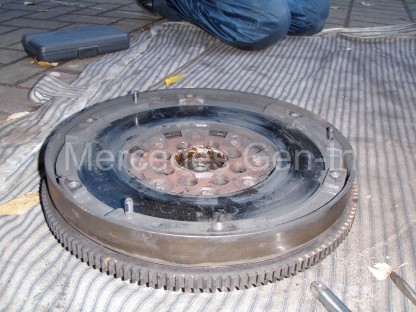
Remove the clutch cover/pressure plate from the DMF, locking the flywheel with a small crow bar or broad screwdriver on the ring gear. You may have to pry the cover off its locating dowels, be aware it is heavy and it could catch you by surprise and fall on you!  Once this is out, you can inspect the flywheel face for damage. The outer DMF section of the flywheel should only rotate independently about 10-15mm in each direction at its circumference in relation to the other fixed half, any more than this indicates the likelihood of a worn DMF.  If you decide to replace this, you will need a long, large torx bit to undo the eight flywheel mounting bolts from the crankshaft. Once removed pry the flywheel from the crankshaft, it sits on a single dowel peg and can take some working to and fro to remove it.   Always inspect the centre bearing in the DMF, if this is damaged it is sadly not available as separate part from Mercedes, only as part of the complete DMF flywheel!  The bearing itself is a special construction of a blind roller bearing made by INA, that acts directly on the input shaft end of the gearbox, this is concentrically inserted into yet another single row ball bearing race which is directly pressed into the DMF.

Replacement of all the parts is exactly as the removal, although be sure to reference the ‘set’ position of the clutch before refitting.

Sprinter gearbox inspection hole and bleed nipple >2006

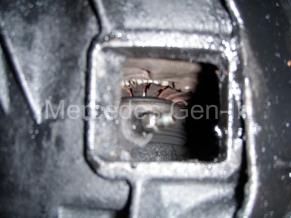
Bleeding the clutch system can only be achieved with a Gunsons EzBleed or other pressure bleeding equipment, no amount of pedal pressing, as you would assume similar to brake systems will not work – trust me, you will be very lucky to achieve success otherwise.  Once you have a good pedal feel and the slave cylinder can be seen to be pressing the diaphragm springs back and forth fully through the inspection hole, start the engine. Now press the clutch pedal several times, you should often hear a light clunk, this is the clutch adjustment ring finding its own position.  Select a gear and test the clutch, all should be well.  If for some reason it appears as if the clutch is not fully disengaging and baulking you from selecting a gear, check your work regarding air in the hydraulic system, if re-bleeding it proves to be good, then try starting the engine in gear, handbrake on, with the clutch down, this will often by inertia, force the adjustment ring from its set position to its new working position, a second pedal press should now settle it into its new operating position and you should have a good responsive light clutch.

VW Crafter Gearbox showing concentric slave cylinder and thrust bearing

I hope you have found this information useful.

Mercedes SLK (R170) ABS Fault – Rear Reluctor Ring (Tone-wheel) Replacement


ABS faults can be complex to solve but often it is the simplest of things that causes those dreaded lamps on the dash.  If there is an issue with any wheel speed sensor arrangement on any corner, then this will prevent a number of things working correctly, namely ABS, TCS, ESP, BAS, Cruise Control/Speed Limiter and on the SLK power operation of the Vario roof too. So it needs to be fixed. It is now also a critical tested component in the UK MOT annual check – any dash warning lamps of this kind will immediately fail the inspection and prevent you from obtaining that valuable certificate.

Mercedes ABS Fault - Reluctor ring replacement 1

Intermittent ABS light faults are often attributed to dirty or poorly adjusted wheel speed sensors, even poor connections or weakly performing/damaged sensors can flag faults.  These faults are usually reasonably cheap to sort, though problems with the pump or controller can run into many hundreds to fix.  With this in mind, it is prudent to always check the simple things first, then move on to the ‘eye-wateringly’ costly parts when all other avenues have been followed and options exhausted.  So where to start…

Fault finding can be very hit and miss without a compatible Fault Code Reader that can access the MB systems protocol. There are many on the market to choose from and probably the most capable will be from the Autel range. Be sure what you are buying covers the ABS system, as often less expensive readers only cover engine fault codes and leave the purchaser no better off when it comes to tracking faults in the ABS, SRS or other Body electronics. I use two or three tools, the most flexible and economical is the Autel 702 Maxi-Diag Elite, this can be purchased for under £150 if you search around for the best deal.

Mercedes ABS Fault - Reluctor ring replacement 2

However if you don’t initially want to run to that expense and you may be able to find a friendly independent mechanic who can read the system for you and tell you where the problem lies.  Do remember that if you go to a dealer for a code read, it is likely to cost around £45 to find where the problem lies.  You will then have to take it back to get the fault cleared once repaired, so as you can see you are getting pretty close to the cost of owning your own powerful diagnostic tool that will stand you in good stead for the future. If you have an older Mercedes vehicle pre 2000, then you will have less choice of code reader and things get a little more complex – you can catch up on older vehicle diagnostics here.

There are common faults that can cause problems throughout the Mercedes model ranges, no different with ABS than any other system. If you get unwanted ABS activation at slow speed, when rolling to a braked stop.  This is often caused by the wheel speed sensor on one or more wheels not detecting its rotational impulse cleanly.  This is called ‘falsing’. The controller is being fed an inaccurate stream of speed signal impulses that makes it think that one of the wheels is skidding and it applies (wrongly) the ABS to that wheel.  On W124 models, this was often caused by the magnetic speed pick up sensor devices on the front wheel hubs attracting metal rust debris, ending up looking rather like a christmas tree of iron filings.  The pulsed electrical induction signal from the sensor as its paired slotted ring on the rotating part of the axle whizzes by, is masked by the ‘growth’ of collected iron and rust on the sensor head, making what should be a very clean and precise tiny electrical signal, into a low level ‘blur’ in layman terms.  Simply removing the sensor and cleaning it up in a great deal of cases will result in a cure for this problem. If this does not cure the issue you will have to look more closely at the condition of the slotted or toothed ring that can be seen at the base of the sensor hole, this part passes the nose of the sensor as the wheel rotates.  On the front wheels of the vehicle this ‘reluctor ring’ or ‘tone wheel’ is often a vertically orientated slotted disk mounted behind the brake disk, attached to the rotating hub. Unless corrosion has taken its toll, the front tone rings seem well protected from the elements and do not often give trouble.

Mercedes ABS Fault - Reluctor ring replacement 3

On the rear, most Mercedes cars have flat slotted punched-out reluctor rings ‘sweated’ onto the outer surface of the outboard CV joint casing, just as it passes through the hub carrier.  Often out of the factory this forms part of the complete half shaft and if it gets damaged a few years down the line, or as it often does – corrodes, then the complete drive shaft/joint had to be replaced at quite a tidy sum.

…Enter the wonderful world of the ‘Far East’ on that popular auction site. A wonderful factory somewhere in the world now produces just the 48 window (slots) 92mm reluctor ring (also common to SL R129 and many others) that you can fit to your existing half shaft and get things going for under £10 component cost. Needless to say it is quite involved to fit as you obviously have to remove the drive shaft from the vehicle to carry this out.  Link to reluctor ring seller.

Mercedes ABS Fault - Reluctor ring replacement 5

This article covers the fitting of a rear drive shaft reluctor ring to a 2001 Mercedes SLK200 R170, though the procedure will be common to many other MB models.  If you discover the faulty ring is on the side that has the exhaust passing by the drive shaft then you have a little more work ahead, as it often involves the partial removal of the exhaust system to obtain full access.  If however, if it is like in this case – on the right rear of the vehicle, no such removal is needed.

Reluctor ring replacement

You may wish to initially remove the wheel sensor to protect it from accidental damage. Then you will need to obtain a 32mm 12 point socket. With the hub centre embellishment removed from the wheel (Alloys), with the handbrake set, in gear, while on the ground, peen out the locking tab on the hub nut.  Fit the socket and with the aid of a breaker bar, remove the centre hub nut from the end of the drive shaft.  Spray a good quantity of penetrating oil onto the shaft end so it travels down the splines within the hub. You may need to slip a tube over the breaker bar to ‘crack’ the hub nut off, as if not recently removed it will be very tight indeed.

Mercedes ABS Fault - Reluctor ring replacement 6

Now raise the vehicle so the differential is at least high enough to be able to swing a 21 inch breaker bar beneath the car (those inboard CV-to-output flange bolts will be incredibly tight) Chock and make sure your working area is safe then remove the 6 reverse torx bolts from the inboard flange of the drive shaft.  These have been thread-locked with a compound that must be the almost as strong as the bolt itself!  It will take some muscle to remove these pins, so be prepared.  Always seat the reverse torx socket on the pin with a copper hammer, not only does this ensure the socket is seated as far as it will go onto the head but the ‘rapping’ helps to jar and break the joint.  Remember – good well fitting tools are important here as if you twist up the head with an ill-fitting socket, you will be left with a huge ‘near impossible’ job to remove it.

Mercedes ABS Fault - Reluctor ring replacement 7

Once all six flange bolts and tri-plates are removed the shaft can be pulled down towards the front of the vehicle.  In some cases you will have to remove the plastic cover over the fuel pump to gain adequate opening to ease out the shaft end.  Its a tight fit, but it will come clear and hang down just below the nose of the diff.  Now take a copper drift and stout hammer and whack the end of the drive shaft, it should with a few blows begin to move, once it starts to move tap it with care so it passes through the splined hub centre.  Support the shaft as you tap and once free, guide it out from beneath the vehicle.  While it is off, check the CV rubber dust boots on both ends for damage/wear/cracks/splits as this is a perfect time to change them.

Mercedes ABS Fault - Reluctor ring replacement 8

Remove all traces of the old reluctor ring and file the surface clean to prepare it to accept the new ring. File deliberately more material off the outer edge to allow a slight taper lead-in for the new ring.  Once you are satisfied that the area is nice and clean and smooth, prepare to tap home the new ring onto the CV joint casing. Heat up the new reluctor ring with a blow torch, don’t go too mad, just enough to make it hot.  Then with a gloved hand, place it centrally and tap gently around the perimeter of the ring to drive it home into position.  In this case it was easy to see the exact location and position of the old ring, if you are not so lucky then use a torch to inspect the opposite side of the vehicle to get the correct placement dimensions you need.

Mercedes ABS Fault - Reluctor ring replacement 9

Once the new ring is fitted, the drive shaft can be assembled back into place and the other parts built up around it, much in the same way as they were removed.  Be sure to tighten the hub nut to the same position as it was prior to removal so the lock tab can be tapped back into place.  If you can obtain 6 new flange bolts for the reassembly, then that would be best, failing that be sure to wire brush the old screw lock compound from the threads before reusing.

Mercedes ABS Fault - Reluctor ring replacement 10

Once the vehicle is back on its wheels on level ground, insert the code reader into the OBDII diagnostics port, then read and clear the ABS speed sensor related faults from the controller. Finally road test. You will most probably now have no warning lights on the dashboard and be able to enjoy once more a fully functioning set of connected vehicle features that were all lost while the fault was present.

SPECIAL NOTES FOR LEFT HAND SIDE RELUCTOR RING REPLACEMENT

Because of the proximity of the exhaust and restrictions of access for the removal of the left hand drive shaft it is possible to remove the lower link bolt (lower wishbone to hub carrier), the ball joint of the tie link and hub end of the pushing link (lowest fixing on the hub carrier)  See diagrams below to identify component attachments to be removed. Once these fixings are removed it is then possible to pull the hub at the bottom just far enough out to allow the drive shaft outer CV joint to slide out its hub spline and hang down to clear the carrier so the new reluctor ring can be fitted.  Just remember to pre load the suspension as if the vehicle was standing on level ground before retightening the removed bolts.  This is a practical alternative method to removing the drive shaft completely from the vehicle.

Fig-117 Fig-116


Mercedes Sprinter – Engine Oil in Coolant Water – Oil Cooler Leak – Fix


As many of you probably know oil seen in the header tank is often the sign of imminent head gasket failure. But before condemning any Mercedes CDI diesel engine to head gasket failure, especially if the vehicle is otherwise running well and not throwing out white smoke from the exhaust or maybe you would have expected to find some water in the oil, there is one place to check first.  The engine oil cooler.

Mercedes Sprinter Oil Cooler Leak Problem 1

The engine oil cooler on Sprinter and other Mercedes CDI engines through the range of commercials and passenger cars is a pancake aluminium pressed fin block, that sits directly behind the oil filter housing on the right side of the engine looking in.  This heat exchanger has two sets of internal galleries, one for engine coolant and the other for engine oil.  This provides conductive cooling of the engine oil shifting its heat to the circulating cooling water system.  What happens is that the internal galleries corrode, usually due to lack of inhibitants in the antifreeze or the mix ratio simply being ‘to weak’ to prevent corrosion. Over time the internal galleries can perforate from one to the other and the resulting high pressure oil in the primary high pressure circuit moving through the oil filter, is forced into the water system and onward to the header tank if it finds an easier path through a pin hole or crack.

Mercedes Sprinter Oil Cooler Leak Problem 2

Depending on the severity of the leak, this can be anything from small trace amounts of oil appearing in the water or as in our case, huge oil migration.  So bad in fact that the driver first discovered that his oil light came on, later when he topped up the oil with over 4 litres it lasted for only 40 minutes of normal driving before the oil light illuminated once more!  When the vehicle came back to the yard we checked the water reserve and it was full to the brim with black ‘tar like’ oil emulsion, so bad that it was clogging the cooling system.

Mercedes Sprinter Oil Cooler Leak Problem 3

On removing the bottom hose from the radiator we drained the system of about 2 litres of oil, we removed about another 3 litres of tar from the expansion tank.  The van ran perfectly in every way except for the massive oil loss into the water system.  Rightly we suspected the culprit to be the oil cooler, as in our opinion, no head gasket failure would act in dumping these quantities of oil in this uncontrolled way.

To remove and replace the oil cooler first drain the coolant system (if you hadn’t already!) Then remove the top induction hose from the intercooler to the inlet manifold for access.  Undo the hose clip and remove the flexible water hose from the oil cooler and tuck it out of the way.  There are five reverse torx oil cooler bolts that are slightly awkward to access that hold the thicker pancake cooler’s back plate to the alloy oil filter casting. Once removed, the cooler can be pulled free, up and out of the engine bay.

Mercedes Sprinter Oil Cooler Leak Problem 4

Often even if you block off and blow air into the water gallery (the cleanest port for your mouth!) of the suspect oil cooler, it is impossible to detect a leak of even the size we had, between oil and water ways. So if you suspect it – change it.  You will always need a new orange sealing gasket to face between the replacement oil cooler and oil filer housing.  It costs around £4.00 and an old gasket should never be fitted, as it rarely seals due to its complexity.  You will most probably need the use of a ‘shaving mirror’ to clean the recess and place the new gasket in its correct positional groove on the rear of the oil filter housing – even a spot of gasket sealer here and there, just to hold it vertically in place while you rebuild, may be required.

Mercedes Sprinter Oil Cooler Leak Problem 5

Lower the new plate cooler into position and carefully push it flat against the gasket on the filter housing, keeping pressure, ‘slide’ the plate to align the fixing holes and refit all the reverse torx holding pins.  Check with a torch that the gasket has not moved during the procedure by looking into the small air gap between the two mating parts, when you are sure all is well, tighten up the bolts.

Mercedes CDI Oil Cooler Gasket

Mercedes Part Number – A6111840280

Refit the flexible coolant hose, put back the induction hose and refill the system with coolant.  Depending on how well you managed to flush the system of old oil, it will find its way into the coolant reserve for a number of weeks.  With a warm engine, squeeze the top hose rhythmically while scraping emerging oil residue from the top of the filler cap.  Keep topping up with water as you go, when you have removed as much of this black sludge as possible, refit the radiator cap and monitor the oil level over the next few days, de-oiling it again when you can.  Eventually it will clear, but it takes time and is dirty work.

Monitor the engine oil level over the next few days to make sure all is well.

Mercedes SLK Vibration on Overrun – All Gears – Propshaft Centre Bearing Replacement


We recently picked up a 2001 facelift Mercedes SLK200 from South Wales and on the way back to Staffordshire it was obvious all was not well with the driveline.  As soon as the vehicle started rolling at even the slowest speeds, there was a bearing noise usually associated with a gearbox problems.  It was present in all gears and became almost unnoticeable at about 60mph and above. It did not change note in any way if you dipped the clutch (This was a 6 speed manual model) or selected neutral whilst rolling.  The only characteristic to this noise was at slower speeds it was slightly lower in tone and when power was applied, even lightly, the noise lessened.  Immediately you had toed-off the power, the noise returned. There was no apparent vibration through the gearstick, although the noise did seem to be coming from the gearbox/transmission tunnel area and was quite loud at sub 35mph speeds.

While this type of noise and the issues connected are discussed in relation to a Mercedes SLK R170, it is probable that similar issues could exist on many models of vehicle not just Mercedes and not specifically just this model.

Mercedes R170 SLK Propshaft

To inspect the propshaft centre bearing it will be necessary to lift the rear of the vehicle onto ramps. Once elevated crawl under the centre of the vehicle with a torch and inspect the centre bearing that you find approximately half way down the propshaft just before its sliding splines.  You should be looking for the prop to be central in the rubber bushing as it passes through. Any sign of sagging downward with the rubber at the bottom of the circular bearing housing, being either split or compressed is a sure sign of a tired support bearing.  Grasp the prop shaft and try and lift it against the supporting bearing, any easy movement here is also pretty indicative of a failing/failed unit.

There is another way of determining wear of the propshaft centre support bearing and that is to elevate one rear wheel and whilst the vehicle is in either park or first (manual box) rotate the wheel.  Get an assistant to look at the centre bearing with a torch. If it is seen to lift as the wheel is turned against the static gearbox the joint must be further inspected.

What actually happens is the propshaft sags in the centre, and on overrun it rotates out of line rather similar to a bent knee.  This induces vibration, this usually lessens when you apply power as the shaft will self-straighten under load and spin centrally once more, only to relax again to the ‘bent knee’ when you lift off the accelerator.  The grinding/whirring noise often heard as soon as you begin to move off, is simply the worn centre bearing race transmitting noise to the transmission tunnel and surrounding chassis through the support bracket.

Worn out propshaft centre support bearing

Turning attention to the ball bearing in the centre of the support, located just as the propshaft section passes through.  If you can see any signs of rusty powder or corrosion dryness this may indicate the races are failing and have become gritty, producing that rubbing worn bearing noise we spoke about earlier.

Mercedes SLK Propshaft Centre Bearing

If you decide to replace the centre bearing it is quite a simple job on the SLK200 R170 and should take no longer than an hour start to finish, other models may involve the removal of some exhaust components to gain full access however assess the job before you start. Begin by undoing and removing the three 19mm nuts and pins that go through the differential input spyder that hold the rubber flex disc.  Now remove the forward rectangular protection plate that bridges the transmission tunnel by removing its four 13mm pins and washers.  Note the position of the captive support spring clip for the oxygen sensor connector, it is attached at the bottom left pin of the plate, if you were lying under the vehicle with your feet towards the front.

Now using tippex or other marking aid, mark off the position of the flex joint and diff input spyder. Pull back the rubber boot that protects the splines on the shaft just ahead of the support bearing, mark the shaft position in relation to the spline position so that on reassembly the two halves can fit together in the exact position as they were in before removal.  Positional marking is important as the propshaft is balanced as a complete unit and if it is assembled differently it could be unbalanced and induce other noise and vibration to the drive-line.

Now remove the two 13mm bolts on the centre bearing yolk.  Grasp the rear section of the prop and push it forward a couple of inches to clear the spigot on the diff input flange.  Once clear of this, the back end can be dropped and pulled free from the spline, withdrawing the complete rear section of shaft with centre bearing attached.  You may have to orientate the bearing to feed it past the exhaust, but in most cases it should not be necessary to remove/part the exhaust for removal of just the rear section.  On the SLK200 2001 facelift R170 you will not have to remove any exhaust component.

Once off the car hold the prop vertically and using a copper drift and stout hammer drive off the centre bearing, invert the propshaft and feed on the new support bearing in the same orientation as the old one was removed and tap it fully home using a similar drift, ensuring you only tap the inner race nearest the shaft to prevent damage.  Once fully seated, the propshaft can be refitted in the same way as removal.

Mercedes drive line flex disc

While you have the rear section of prop off the car, this is a great opportunity to inspect the condition of the rubber flex disc on the drive line.  You are looking for failure in the form of ‘C’ shaped cracks appearing around the bushes that allow fixing to the drive flanges.  Any problems here can be addressed by fitting new flex discs, obviously the front unit would be accessed by removal from the gearbox output shaft. It is more probable that the rear flex disc exhibits more wear than the front due to its position on the vehicle so use the rear disc as a visual indicator of what the front may be like, from this determine if further inspection is necessary.  When removing/replacing rubber flex discs it is important to note the moulded arrows on the rubber outer edge. These indicate the fixing bolt orientation with regard to where the nut of the through-fixing should be on reassembly – Arrow points to nut.

Mercedes Vito (W639) Manual Mirror Replacement


This is just a quick overview on how to replace the manual drivers (or passengers) door mirror on the Mercedes Vito W639. Written below is a brief run-down on how I replaced the door mirror. Not a massively technical job, I know, but may be useful for people who are a little wary about pulling the trim off.  The first thing you need to do is to carefully remove the plastic trim (shown inside the yellow rectangle on the photo below) that runs from the front/top of the door panel and all the way up to the top leading edge of the inner door frame.

The 2 yellow dots show the approximate location of these clips. Take care when removing to protect the trim, if possible, as my trim came off and left the clips still located in the door. Fortunately, the mounting points were not badly damaged and I was able to relocate them without any problems.

Mercedes Vito W639 Manual Door Mirror Replacement 1

The 2 clips that hold the panel in place are metal spring clips and these are located into small mouldings in the trim panel itself. Images below show the top and bottom clips, respectively, after I had relocated them.

Mercedes Vito W639 Manual Door Mirror Replacement 2

Once the trim has been removed, you will now see the third mirror mounting bolt and the 2 locating holes for the clips.

Mercedes Vito W639 Manual Door Mirror Replacement 3

Remove all 3 mirror housing bolts, being careful to support the door mirror to prevent damage to the mirror, or the door.

Mercedes Vito W639 Manual Door Mirror Replacement 5

And in the traditional vein of the Haynes manual, refitting is the reverse of removal!


The above article was submitted to Mercedes Gen-In with thanks to:
Peter Johnson of ‘Enhance With Vinyl’  
www.enhancewithvinyl.com