Author: Steve Ball

Cargo area lighting control modification from Sprinter cab dome light (Models to 2006)


Having a large fleet of Sprinter vehicles running on delivery routes has its problems and one reoccurring issue is the cargo area lighting being left on over the weekend and flattening the battery. Come six o’clock Monday morning the driver rings the boss to say his vehicle wont start off the lot.

The issue really is I suppose mainly that the cargo area door pin switches get damaged both through worn fold back rear door hinges and clumsy forklift loading, worn ill-fitting doors continually not helping the situation.

mercedes pin switch

What happens is each of the rear interior light unit switches gets set to middle position (off) during the day and as unloading at the depot is done in the evening the switches are moved to the permanent on position to illuminate work. Obviously this is forgotten about when the doors are shut and they drive back to the parking lot at the end of the day. The van is then locked, keys placed at the lodge and off home the driver goes – lights still on.

So how do you modify the rear interior lighting so this does not happen? Lets take a look at how the current set up works.

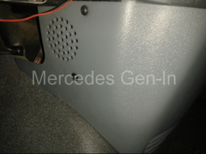
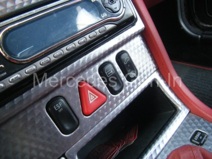
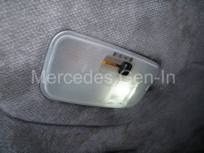
Each of the three rear light units can be operated separately by their own wheel control. – Central position Off. Permanently On, or On when a door is open (pin switch activation)

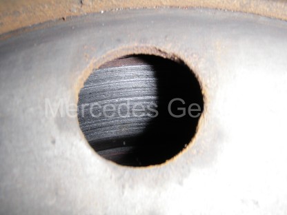
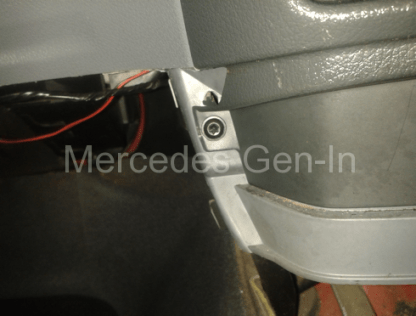
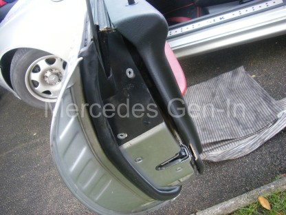
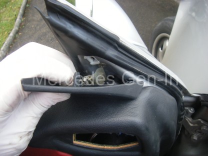
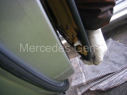
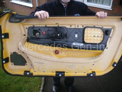
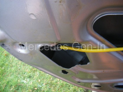
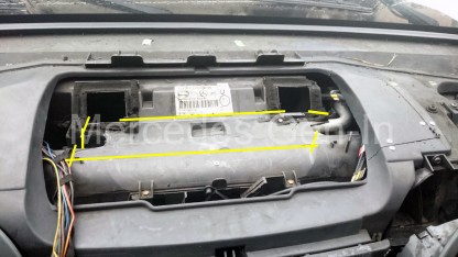
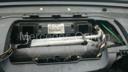
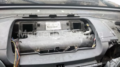
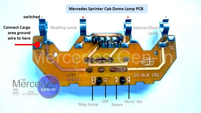
There are three wire terminations to the rear of the lamp assembly; these are plugged into the loom via a three pole-latching plug. To gain access to the rear of the unit and the connector, use a screwdriver to prize the right hand edge of the plastic lamp to the left and lever it out of the pocket in the steel body. Be careful as the central copper band you can see on the back of the lamp is live 12v supply and can short on the body if you do not observe some caution when taking out the lamp unit.

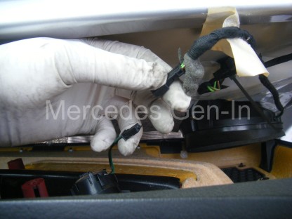
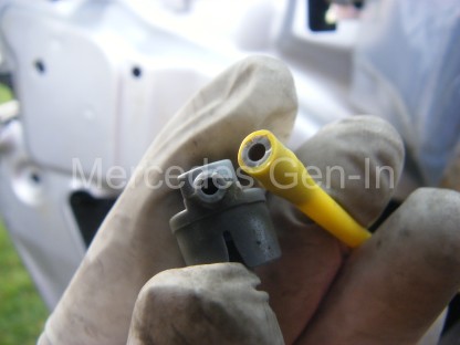
Once out of the body you can identify the wires into the plug by the following descriptions.

Nearest the connector plug latch you have: Brown (ground),
The middle wire: Red-Yellow (supply)
Furthest wire away from the plug latch: Brown-White (ground via pin switch)


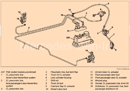
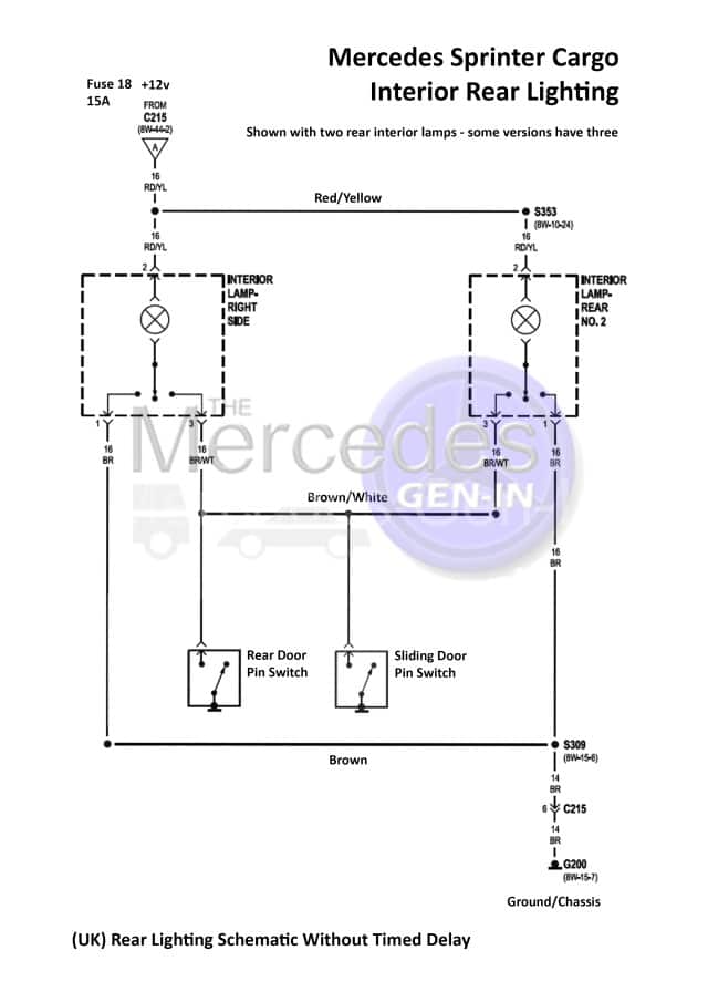
Below is the common schematic for UK Mercedes Sprinter vans without the timed delay illumination option (most pre 2006 cargo vans)

sprinter cargo lamp modification 1

What was required was a way to indicate that the rear lamps were on behind the full bulkhead from the driver compartment, even better if all the lights in the cargo area could be isolated (switched on and off) from the cab.

sprinter cargo lamp modification 2

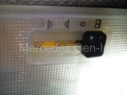
Investigation of the dome lamp in the cab area found that it had two lighting circuits included within. The first, left hand lamp in the dome operates like the rear cargo lights, switch positions for Off, On, or On with front cab doors open. If you were to push the slider switch to the (Book/Map Icon) this illuminates a separate lamp in the dome that is magnified with a clear lens for map reading – adapting this switch position to control all the rear cargo lights is a perfect solution as it provides manual control and a visual indication (map light) that the rear lamps are powered. Turning off the map light in the cab ensures all the rear lighting is off and not draining the battery unseen.

sprinter cargo lamp modification 3

Because all the interior lamps are fed with a constant supply to their switches, grounded by either a door opening or selecting ‘ON’ on their individual switches, lamp control can be done in two ways.

1- Switching the common live supply to all interior lighting
2- Switching the ground to supply to all interior lighting

As the live supply is common and fused through Fuse 18 (15A) any switch in this circuit would remove power from all interior lighting, including the front dome lamp. Power to the cargo lamps is split into two sections of loom running down both the left and right side of the vehicle on the mid level box section, so adding a switch to live supply here is not straight forward.

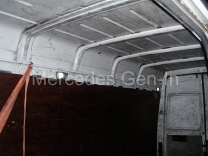
The solution is to switch the grounds to all rear cargo lighting from the front dome lamp when in the ‘map reading’ position. To achieve this you will first have to run a new common cable between all lamps that will become your cab-switched ground. This can be fed down the cab headlining to exit at the dome lamp and run to each of the rear lights in turn. It is possible to thread the wire over and inside one of the roof supports to reach the light behind the sliding door pillar.

Because of the repeated damage to the pin switches on the doors and the nature of the use of the vans for multi-drop delivery, we no longer required the lights to come on with a door open in the rear area. What was preferred was that the driver switched on the rear lights from the cab before entering. Once he got back into the cab he would turn off the lights on the dome light switch. Should he leave the lights on in the rear the front map light would be illuminated warning him to the fact.

Sprinter Dome Lamp

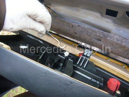
Modifying the connections to each the rear lamps was simple. Cut the Brown/White wires from the plug and tape the ends, this disconnects the door pin switches. Then cut the existing Brown (ground) wire a couple of inches back from the connector and tape the loom. Now connect your new common ground to the short stub of brown wire from the plug using insulated wire-crimps.

Once all three cargo lights have been modified place their wheel switches into the permanently on position. Each lamp can still individually be turned off and isolated if needed by selecting the middle or door pin position.

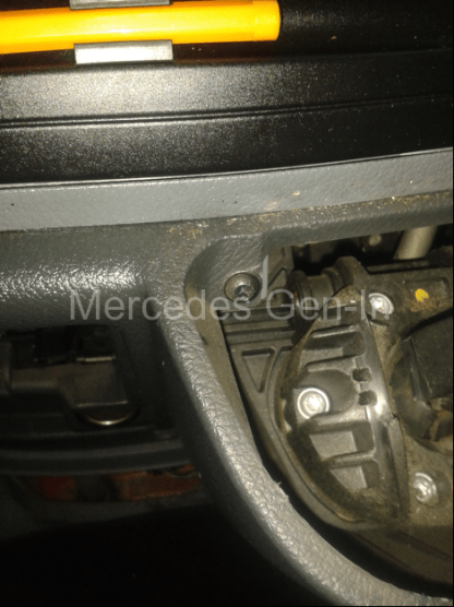
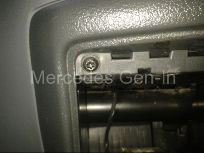
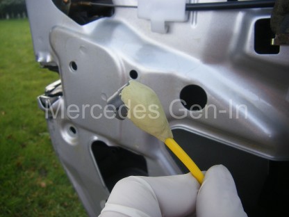
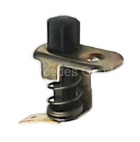
Within the front dome light correctly identify the map reading bulb, this festoon lamp will be held in position by two spring clips on the PCB. Identify the outermost pointing clip holding the festoon lamp and carefully solder the new common earth cable you have run from the rear compartment to this point. Be sure to solder it to the outside part of the clip to maintain a good connection of the clip to the map bulb. (See photograph above)

Having dismantled the switch and looked how the switch functions I have determined that this point gets grounded when the switch is placed in the map light position – perfect for what we require! You could if you wished check this out on your own dome light with a test meter just to confirm your configuration is identical.

Once connected, the front dome light can be clipped back into position.

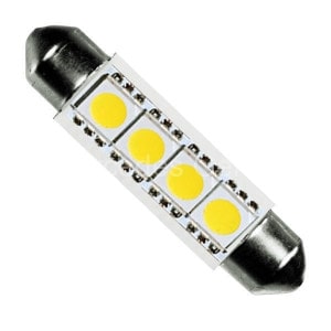
We decided to replace the existing festoon bulbs with LED types. This has two benefits for us. The first is that the light from the lamps is brighter than standard bulbs and also the total current drawn is substantially less, further ensuring that there is no chance of overrating the front dome light switch.

sprinter cargo lamp modification 4

LED bulbs were fitted to the rear light units and they were tested and clipped back into place. It worked perfectly. A few moments with the driver to explain how the new lighting worked and they were pleased with the outcome. As the vehicles are parked on a secure compound at night we briefed the security guard that should he see any interior lamps showing on in the cabs after dark (that he can see from his lodge) he would turn them off. We now know that with this modification that if there is no light on in the front of the cab the cargo area is also in darkness and we are doubly assured the van will start with a healthy battery after standing a few days.

led festoon lamp Sprinter

This modification may not suit everyone’s application but for the delivery vehicles on our fleet it was well worth the one-hour investment to modify the circuit. It is also unsuitable for later models fitted with interior light delay timers, as they are more complex and controlled by an electronic module and would not lend themselves to this type of modification.

Mercedes Sprinter – Scraping noise from front brakes – Brake pad replacement


A customers Sprinter MWB van pulled onto the yard and as it slowed to halt it made a loud metal-on-metal scraping sound.  The driver leapt out and explained the noise, which really did not need any explaining!  He had just ‘popped in’ to get it fixed before he continued on his 150 mile round trip delivery run before the closedown for Christmas.

Mercedes Sprinter Front Brake Pad Replacement 1

Looking at the rust coloured dust deposited on the front wheel rim it was obvious it was the front pads that were ‘non-existent’, closer inspection revealed that the near side pad set was so worn the steel backing had begun to score the outer face of the brake disc.  With little to no time to do a complete repair, the object was to get him safely on his way and revisit the repair with ordered and supplied replacement brake discs in the New Year. So a quick pad change was needed… Hopefully this will explain how to do this.

Mercedes Sprinter Front Brake Pad Replacement 2

While the vehicle is still on the ground, use your ‘weapon of choice’ on the wheel studs. In our case this is a 1 inch drive socket bar with 19mm socket and long ‘slipper’ tube for extra leverage . It was used on both front wheel bolt sets before lifting the vehicle with the trolley jack. If you get a stubborn wheel bolt, take the largest hammer in the tool box and hit the head of the wheel bolt ‘square on’ as hard as you can at least a couple of times, try again with the bar and often this is all that is needed to free off the bolt.

Mercedes Sprinter Front Brake Pad Replacement 3

Once in the air, (A good safe place to locate the trolley jack cup on either side, is under the triangular steel spring clamp plates bolted to the front subframe) take off the wheel and turn the steering to orientate the brake caliper as far out from under the wheel arch as possible.  Pull out both upper and lower bungs from the ends of the slide pin rubber weather shields at the rear and using a 7mm hexagon wrench undo both slide pins and remove them.

Mercedes Sprinter Front Brake Pad Replacement 4

Using two stout screwdrivers release the rattle spring from the face of the caliper by prying it away from the disc while releasing the hooked ears from their locating holes in the sliding portion of the brake (two photos down).  Once removed place to one side.  Again use a stout screwdriver or lever to push back the hydraulic piston into the caliper. Once this is almost flush with the casting, you are assured that the new pads will slot straight in without problem.

Mercedes Sprinter Front Brake Pad Replacement 5

Remove the sliding part of the caliper and place it on the top of the steering knuckle so that the flexible hose is not stressed in any way. The inboard brake pad will still be attached to the caliper piston with a three pronged spring affair.  Simply pull out the pad from this locator and discard it, do the same with the outboard pad that is probably still sitting in its slots on the hanger casting.  It is worth cleaning the rust from the brake disc at this point as the new pads will bed in quicker.  You can do this by striking gently the outside edge of the disc working your way around its circumference to break away the accumulated scale and rust, finishing off with a file to remove any lips formed on the braking surface.  Finally clean off with a scraper or wire brush the sliding surfaces where the pads touch/rest on the casting of the caliper and then apply a thin smear of brake grease to these points.  In this case, as I was to be revisiting the repair in just a few days, I did not use any grease and just slotted in the new pad set.

Mercedes Sprinter Front Brake Pad Replacement 6

Offer up the caliper sliding section and when it is fitted snugly, replace the two slide pins using the 7mm hex wrench.  If the slide pins are dirty clean them up with a wire brush and also apply a light coating of brake grease before assembly. Tighten both slide pins and replace the plastic bungs.  Now replace the rattle spring, locating it into its two holes and making sure the two long sprung arms of the leaf spring are located behind the fixed part of the carrier (the hanger) to apply the necessary pressure.

Mercedes Sprinter Front Brake Pad Replacement 7

Mercedes Sprinter Front Brake Pad Replacement 8

Hop into the cab and ‘pad’ the brake pedal in short pumps to seat the pads against the disc, and then check your work. Once satisfied replace the road wheel and lower the jack.  Continue to change the pads in the other side to complete the job.

In this case the brake disc is badly scored and really should not have had just pads fitted without replacing the brake disc itself.  Bedding in time, pad wear and brake efficiency will ultimately be effected.  Just replacing the pads in a situation like this should only be done in a ‘get-you-by’ situation and driven onward with care until the earliest time you can replace the discs/pads as a set. (You will also need yet another new set of brake pads to compliment the fresh brake discs you will be fitting)

Mercedes Sprinter Front Brake Pad Replacement 9

There is fitted to this model and all Mercedes vehicles, a pad wear sensor, this had a broken wire at the caliper and because it is of the earlier single wire type, no dash indication of ‘pad-low’ was shown (the indicator relies soley on the single sensor wire contacting ground to illuminate the dash lamp, this would happen as the pad wears down below the pocket in the pad material where the sensor tip is located, eventually touching and grounding it to the brake disc surface).  The later ‘two wire’ sensor versions, as fitted to 2006 on vehicles NCV3 Sprinter and W639 Vito etc, display a lamp if the sensor circuit is broken or grounded, which in turn reduces the chances of the above occurring without warning.  See this posting on wear sensor replacement.

Adjusting the (W639) Mercedes Vito Reverse Lamp Switch


This is a quick overview on how to replace, or adjust, the reverse light switch on the Mercedes Vito W639. to address issues I was having where my reverse lights weren’t coming on all of the time.

If I wiggled the gearstick around the reverse/neutral position, they would flick on and off intermittently. So the switch was (sort of) working and I also knew the fuses/bulbs were okay. So I decided to try and check the reverse light switch adjustment.

The switch is actually located inside the vehicle about 6 inches below the gear lever, behind the lower facia. To actually get to it wasn’t too difficult. The first thing to do was to remove the lower centre panel, this is only held on by 2x torx screws (T25 in my case) on each side.

Mercedes Vito W639 Reverse Lamp Switch Adjustment 1

Fig.1

Once that panel was removed, I took out the ash-tray and removed the surround from around the gear lever. This is just clipped in and should pull free without too much effort.  This should now allow you access to the 5 torx screws (still T25) that hold in this console.

There are 2 lower screws at each side (Fig 2), 2 just inside and behind the gear lever enclosure (Fig 3) and one at the top left (Fig 4).

Mercedes Vito W639 Reverse Lamp Switch Adjustment 2

Fig. 2

Mercedes Vito W639 Reverse Lamp Switch Adjustment 3

Fig. 3

Mercedes Vito W639 Reverse Lamp Switch Adjustment 4

Fig. 4

Once these screws have been removed you should be able to pull the facia away from the dashboard. There are just 4 locating clips (2 on either side) now holding it in. NOTE: Only pull the console out far enough so that you can remove the plug from the rear of the cigarette lighter before fully removing.  When the console has been removed, you should now be able to see the reverse light switch to the right and below the gear lever (right-hand drive vehicles) Fig 5.

Mercedes Vito W639 Reverse Lamp Switch Adjustment 5

Fig. 5

In the next photos, I have tried to show what is supposed to happen when you select reverse gear.

The flat plastic ‘shelf’ is supposed to push up against a sort of ‘L’ shaped spring steel lever (Fig 6) which, in turn, pushes up against a small micro-switch which is then supposed to turn on the reverse lights (Fig 7).  In Fig 7, the reverse light switch has been removed for clarity just to show in detail the steel lever and Micro-switch assembly.

Mercedes Vito W639 Reverse Lamp Switch Adjustment 6

Fig. 6

Mercedes Vito W639 Reverse Lamp Switch Adjustment 7

Fig. 7

Once I had taken the switch off, I simply (and carefully) bent it slightly downwards so that it made contact with the flat plastic ‘shelf’ section on the gear linkage. Refitted the switch and tested. All worked well and in the traditional vein of the Haynes manual, refitting was the reverse of removal. Although I’ve just realised, I forgot to re-connect the cigarette lighter !

Pete Johnson.

The above article was submitted to Mercedes Gen-In with thanks to:
Peter Johnson of ‘Enhance With Vinyl’
www.enhancewithvinyl.com

Mercedes SLK (R170) Central Locking Problems Resolved


Central locking problems in the R170 series of Mercedes Benz SLK are quite common. The issues are usually centred around the failure of the PSE (Pneumatic System Equipment) pump unit or its connecting air pipework. The pneumatic door lock actuators are simple by design and as a result are found reliable, even in older cars.

Mercedes SLK Central Locking Fix 1


If your central locking is playing up, maybe no doors lock or unlock, perhaps one door does not function, there are a few simple checks to determine what and where the issue may lie. The first thing to try is when you lock the car from the remote key fob – does the vehicle respond and if the ‘alarm arms and disarms’ this is an indication that the key fob is sending the correct signals to the car. However if the car only either locks or unlocks from the fob, there is a chance the fob has a problem with one of the miniature tactile switches inside. These often fall off or break away from the internal PCB, these can usually be repaired (re-soldered or replaced) by carefully breaking open the sealed halves of the fob and resealing when done.

Mercedes SLK Central Locking Fix 2

Actuating a fully functioning key fob will cause the PSE pump to run for a period, as will unlocking the drivers door, opening the drivers or passenger door, unlocking the boot or operating the dash ‘door lock’ switch. Listen out for the pump motor running in the area of the boot floor just below the rear of the fuel filler. To inspect the PSE pump unit, open the boot and remove the spare wheel, then remove the right hand plastic trim lower edge fasteners to enable the ‘foam box’ containing the PSE pump unit to be extracted sideways. There should be enough free-length in the wiring loom and yellow connecting pipes to allow its partial removal into the spare wheel well. If the foam box is ‘wet’ and you do not hear the pump run on lock actuation, then prepare yourself for a potential financial blow.(Circa £200 – £380 for a good used part) It is common for the PSE pump unit to be waterlogged from either water entering the boot from the inner arch area (corrosion) or through faulty boot lid seals and block channel drains (drains behind rear quarter glass gutter, under boot lid) – either way the water is mopped-up by the pump unit foam and damage results. Housed in the base of the PSE unit is a complex electronic PCB that controls its cycle and air distribution sequence. Even if not completely waterlogged a damp environment can do its worst, not only to the PCB but also to the small DC motor that runs the pump itself. It is worth checking the supply fuse, but often no response means replacement required. There are a few companies offering a service exchange service for PSE pumps but as yet I have not found one that does R170 types!

Mercedes SLK Central Locking Fix 3


However if the motor ‘runs’ and seems to run at a healthy speed (buzz) you may be in luck. Mark the yellow hoses and their associated clip in connection points before removing them from the pump block. Activate the pump and see what degree of suction or pressure appears at the air manifold output spigot connections. Suck locks, blow unlocks. The three yellow pipes are connected to: The drivers door only, the passenger door and boot lock and finally the fuel filler flap and cubby box lid lock. You can manually test the function of the actuators on these components by sucking and blowing on the individual pipe ends. This takes a bit of ‘puff’ but it can be done. If when blowing on the respective pipes, you can blow constantly, without building any pressure in the pipe, there is most likely a leak. The pipes are made from a semi rigid wall Nylon and very tough, it is uncommon for them to split or cut. What is more common and is actually a design flaw in this model, is the grey right angle pipe end connectors that clip to the door lock actuators, break. This is due to the over-tight stretch of the air pipe across the door inner. Over time this work-hardens the connector (door slamming etc) and the connecting pipe breaks away, taking with it the plastic spigot on the grey push-on connector. Any air leak will affect the function of the locking. Often if you listen carefully at the latch section on the door edge while the pump is running, any hissing is a sure indication that the pipe connector has broken inside the door and will need attention.

Mercedes SLK Central Locking Fix 5

To gain access to the door lock actuator and its yellow pipework you will have to remove the door card. Start by prizing out the SRS badge and removing the philips screw behind, then remove the chrome trim plate and plastic latch aperture cover from the door edge. Beneath the door handle locate the slot in the underside seam and insert a broad screwdriver, lever off the top half of the handle cover to reveal two more large philips screws. This will take some force to unclip the handle and you may think you are about to break it – don’t worry as long as your screwdriver is as broad as the slot will allow it will pop off – eventually!

Mercedes SLK Central Locking Fix 6

Remove the top triangular trim piece behind the mirror area. Using a trim clip tool or spatula, unclip the trim at its lower edge and speaker section. You can see the position of the mushroom clips in the photograph of the rear of the door card.

Mercedes SLK Central Locking Fix 7

With the bottom edge of the door free lift the handle of the door card upward with some force. Ensure that when the large handle clip disengages from the steel panel of the door, that you don’t stress the tweeter speaker wire, this could if yanked, break the fine wires to the speaker.

Mercedes SLK Central Locking Fix 8Mercedes SLK Central Locking Fix 9

Once the door card is free, slip your hand behind and disconnect the tweeter connector (covered in grey foam) and then unclip the door release lever mechanism hook from its operating lever, you will have to pull back the black outer sleeve of the bowden cable and slide it from its retaining slot in the plastic block on the rear of the door card. Now you can put the door card safely out of the way.

Mercedes SLK Central Locking Fix 10

Carefully peel back the plastic membrane from the lock area of the door to reveal the actuator and yellow pipe. Operate the lock from the dash or key and identify the leaks in the area where the pipe joins to the grey push on connector. Usually once you touch this area the pipe breaks off completely! The connector can be levered from the actuator with a screwdriver, it is a snap fit.

Mercedes SLK Central Locking Fix 11Mercedes SLK Central Locking Fix 12

While you can no doubt get replacement grey push connectors for the air pipe, if you damage the pipe end in replacing it and have to cut it back even a few millimetres, it will be too short to reach the actuator. The pipe appears to be heated and sweated onto the connector and I felt it too much of a risk to try to replace the connector in this instance, so I repaired it in such a way as it would be stronger than the original part!

Mercedes SLK Central Locking Fix 13

It is important to release the yellow pipe from the cable tie that also holds the loom section a little further across the door, this gives a few valuable millimetres of slack to take the stress off the pipe and its connector.

Mercedes SLK Central Locking Fix 14

Now to repair the connector. Using a jewellers screwdriver or suitable size small drill, open out the plastic connector ‘break-point’ and pipe to take a short piece of nozzle tube cut from a WD-40 spray can. This tube can be scraped with a sharp knife to reduce its external diameter slightly to obtain a tight push fit inside the two broken pieces of the connector. A piece of about 8mm in length is perfect, using a light smear of bonding glue on assembly if you wished.

Mercedes SLK Central Locking Fix 15Mercedes SLK Central Locking Fix 16

You will now have to mix some epoxy putty (Milliput) to add strength to the join area and complete the repair. If you shape the putty as I have done in the photographs, it will add support for the pipe and prevent the two pieces coming apart in the future, while additionally of course sealing the repaired joint. Once you have fashioned your repair, push the connector back home onto the lock actuator.

Mercedes SLK Central Locking Fix 17

Test your locking and build up the door. I suppose if you were a purist you could try and replace the connector with a new part, but due to the restricted pipe length (the real problem in the first place) you could run the risk of damage. As the repair cannot be seen, in my view it is a simple and quick solution to the problem. This repair technique could be easily used on connectors utilised on the pneumatic headlamp levellers on vehicles of the same era, such as the R129 SL etc.

SLK PSE Central Locking Pipework Connection Scheme

SLK PSE Central Locking Air Pipework Connection Scheme (LHD Models)

SLK Electrical Device Connection/Integration Scheme

SLK PSE Pump Electrical Device Interconnection Scheme

See here for more useful general background info on the Mercedes pneumatic central locking system.

Mercedes Sprinter Cabin Heater Not Getting Warm – Heater Matrix Replacement


This article is specific to the Right hand drive (Left hand drive should be similar) Mercedes Sprinter pre 2006, T1N, without air conditioning or Automatic temperature control (ATC)

Well, winter is here again and one of the long wheel base 2005 Mercedes Sprinters had been running cool in the cabin heater department for some weeks, it had now got to the point the driver was complaining about the cold so we were compelled to take a look.

Sprinter Dash panel removal

The first port of call was to change the engine coolant thermostat, as it was running cool on the gauge, so needed that job doing anyway.  Needless to say in doing so, there was no improvement to the cabin temperature and further investigation was needed.

Both the supply and return pipes to the heater matrix under the bulkhead, engine side, were very warm – so hot water was obviously making it to the cabin heater.  This particular van had the diesel-fired coolant ‘pre-heater’ removed (ESPAR) from the front left inner wing and all the steel pipe bypassed, as it had started to rot and leak in several places.  This is quite common on older Sprinters and this steel rigid pipework runs mostly out of sight behind the bodywork, up above the heater blower housing.  This makes it near impossible to detect any leaks, let alone repair it, so it had been bypassed some time back as a repair measure.

Removing the front dash panel inside the cab and dropping forward the heater controls to check the flap and valve controls, proved that all was well here and the supply valve in particular (green actuator cable jacket) was working correctly, opening and closing the supply water valve to the matrix.  Often the rotary heater control that varies the temperature is broken, not allowing the cable to push back inside the outer to actuate the valve fully open.  There is a steel clip and plastic retaining moulding that breaks away from the control panel, rendering the rotary control unless often resulting in a complete replacement control panel being required. (£££)

The next stage is to remove the top dash section that houses the radio binnacle, this is held with fixings behind the speaker grilles left and right, along with various other fixing screws following the front edge of the dash lip.  You will need to remove the speedo front trim and the back cover – the instruments need not be removed.  Once this is removed you can now see the top of the heater box and in a small open void to the right, the aluminium supply and return pipes routed to the heater matrix.  Extending a finger to touch the supply and return proved that both were scorching hot, indicating the heater valve was open and water was at least circulating this far.  Extending a finger inside the square fresh air ducts and hooking it back to the cabin, you will find a small section of plastic housing missing. This enables you to actually touch the heater matrix element – on the left and right sides these were cold! – even though the flow and return pipes were boiling hot.  This indicated that coolant flow through the heater matrix was restricted and in effect the water was just flowing in and straight out without causing any part of the radiator section to warm, thus no cabin heat.  Its worth noting that if you have the fan off, the matrix will eventually warm through but with the fan running, as soon as air begins to flow across the matrix it rapidly chills it to an almost non-existent heat. No warn water conduction.

So we need to change the heater matrix.  What a huge job. The complete dashboard has to be removed, including steering column to gain access to the heater box.  The heater box itself then has to be split into two halves to replace the heater matrix inside.  That can take anywhere between 8 to 10 hours to complete, we did not have the time available and the van was due out in a short number of hours.

The tools you will require are a battery drill, 1/8 inch drill bit, sturdy flat blade screwdriver, hacksaw blade, 6mm 1/4 drive socket and ratchet, aluminium strip, pop rivets (or self tapping screws) and silicone sealant.

Sprinter Heater Matrix removal 1

Drill a small row of holes in the top of the plastic heater box to enable you to insert a hacksaw blade and cut along where the yellow lines are indicated on the image below.  Take care when drilling and sawing to only cut the plastic box and nothing beneath. You will be fairly safe if you cut only where the yellow lines indicate.  Once you have cut along the top of the box, use a broad screwdriver to remove the cut section, you may have to lever and snap away a small section of plastic that remains from either side of the top section so that it can be lifted away.  It should now look like this.

Sprinter Heater Matrix removal 2

Now you will need to cut a small section from the right of the grey dash under-layer to gain full access to the three 6mm pins that hold the compression plate connecting  the heater matrix pipe spigots to the valve body, this is clamped against captive nuts in the plastic water valve flange assembly.   The extra access section on the right you will need to cut away can be seen by comparing the two photographs above.  Once the three 6mm pins and plate are removed drain down some coolant from the system, the easiest way to achieve this is to simply remove the thermostat bypass hose.  This joins the thermostat housing to the coolant expansion bottle, once this has drained down carefully pull the matrix pipes out from the valve block (there is just enough clearance).  There is a swaged end and rubber O ring on each pipe, make sure you do not damage them. While holding the pipes pulled free from the valve block, pull the heater matrix up and out of the heater box.  Either replace the heater matrix with a new/replacement unit or back flush the original unit upside down, tapping it to loosen the collected scale and rust that finds its way into the matrix tubes.  Most of the rust and debris I am sure, came from the decomposition of the steel circulation pipes mentioned earlier.  It is worth mentioning that to simply flush the matrix from under the bonnet/hood in situ would achieve very little, as the unit has to be inverted to dislodge any accumulated debris or silt. There is no true ‘inlet’ and ‘outlet’ with a totally chambered enclosed flow between the two, heating water simply enters the header at the top and exits further along its length.  A great deal of the heating of the matrix is mainly by conduction in the heated water down through the matrix tubes beneath the header.

Sprinter Heater Matrix

Install the newly flushed heater matrix, refill the coolant system and test your repair, the matrix should now be evenly very hot all over its surfaces and not just the top header section.  If this was a success with no leaks, rebuild the heater box using small cut aluminium plates and pop rivets, making sure to close up the saw cuts as well as possible and restore as close as possible the original shape of the heater box.  Apply a smear of silicone sealant to the saw cuts making good any air gaps that remain.  Once the sealer has dried, rebuild the dashboard top section and replace the heater panel and front trim.

Job done – all your handy-work is completely hidden under the top dash cover – nothing is visible to the naked eye, revealing anything other that you did not take out the complete dashboard to replace the matrix!

Sprinter Heater Matrix removal 3

Time taken 3 hours vs 8-10 hours labour – make your own mind up!