Technical Vito W639

Technical Vito W639

Binding or sticking front brake – Vito W639


I recently noticed that the driver side front brake caliper was sticking on my 2008 111 Vito (W639).  It got so bad and jammed on that it began to ‘cook’ the brake pads and smoked, burning hot!  I limped the vehicle home and when all had cooled down a little set to work on investigating.

DSC_3057

Even before the wheel was removed the caliper slides were suspected to be binding on their surfaces preventing free side to side movement of the floating part of the caliper casting.  Removing the two long 7mm hex screws under the rubber protective caps, top and bottom at the rear of the caliper, revealed sure enough that the lower slide was rusted solid into the casting.  Fortunately I had a suitable 1/2 inch copper drift to hand that I used with a hammer to drive out the rusted slide from the casting.  I cleaned up the surface of the slide pin with a very fine file and wet and dry abrasive paper, and treated the inside of the casting to a similar clean-up.  Using anti-seize copper grease they were reassembled with ease and now moved freely.  If badly corroded, new slides would have to be purchased.

DSC_3058

On reassembly I noticed that the lower of the two pistons in the caliper was sticking too, probably due to the fact that it had been locked in one position for a while caused by the seized slide.  Peeling back the piston dust seal I was able to squirt some WD40 into the gap between the piston and casting.  Working the piston back and forth with a piston compressor or ‘G’ clamp I was able to free it off completely.  Pumping the brake pedal 5-6 times 3/4 of the pedal stroke will extend the piston far enough out of the caliper to attend to its chromed surface with fine emery cloth or wire wool (lightly!).  Be sure to block the second piston from extending while you do this.

DSC_3068

As my piston was well extended and exercised over a 1″ extension from the casting I was able with the careful use of slide grips on the very outer rim, external to the dust seal, to rotate the offending piston by about 90 degrees to hopefully shift any slight piston corrosion areas to another point on the caliper bore and thus give a better chance of it not sticking again in the future (Maybe!).  If the corrosion was severe and the piston did not free up after a reasonable time I would recommend fitting replacement calipers as experience tells that these faults often return.

DSC_3063

Building back up the drivers side and refitting the wheel, I moved to attend to the other side as a precautionary measure.  Never do brake work to one side of a vehicle, especially the front without at least inspecting the other hand for similar or related problems.  If you ignore this there is a chance your braking could be imbalanced or grab/snatch unevenly under heavy braking.  A good road test proved all was well and  I now relax awaiting tomorrows job list….

Additional post:

12 months later the sticking/binding returned, I decided to pump out the pistons to almost fully extended.  I then clamped the brake hose and pulled both of the pistons from the caliper.  Using a sharp pick or small screwdriver carefully remove the rubber seals from the casting. If the seals are not damaged, they can be cleaned up and replaced into their respective grooves when rebuilt.  However the major problem here is corrosion behind the seal that ‘packs it out’ and tightens it to the piston – causing the piston to stick.  Once the piston and seal is removed all the rust, muck and debris can be raked from the back of the seal groove and cleaned up with fresh brake fluid and a lint-free rag.  Replace the rubber seal and insert the pistons fully home.  If the pistons need cleaning up use fine wire wool.

Once the caliper is back in place, open the bleed valve (11mm) a hexagon socket is the best tool to prevent rounding as it is likely to be corroded. Wait until fluid emerges then tap the casting with a light hammer to release trapped air bubbles.  When the brake fluid runs without bubbles close the bleed nipple and push the brake pedal to bring the pads in contact with the disc.  Reopen the nipple and push the caliper back ejecting fluid as you go, retighten the bleed nipple and build up the wheel, not forgetting to top up the brake fluid reservoir.

While I was in the area I also re-greased the caliper slides before reassembly.  A road test proved all to well.

Service Indicator Reset Vito W639 111 (2008)


If you are reading this you may have been irritated by the huge number and range of methods described to reset the service indicator (ASSYST) on the 2008 (or thereabout) 111 Vito (W639).  Most of the methods  described on the web, in the most part, offered by well-meaning people who have incorrectly read or copied the incorrect information from somewhere then relayed it via a post on a forum to someone asking for help.  The truth is, there are a few dashboard/instrument cluster versions in the W639 range and it changed version in this year for the basic van (single semi circular speedo to twin circular dial) – most get it wrong and to find the correct method for resetting with this twin dial type of dashboard without steering wheel controls, is rare to find and at the very least may prevent you some irritation by having to try method after method finding that they simply do not work!

So here it is:  If you have specifically a 2008 Vito 111 (W639) and your instrument pod is like this one below, with no steering wheel control buttons…..

Vito 111 2008 (w639) Instrument Cluster

Vito 111 2008 (w639) Instrument Cluster


….then the ‘tried and tested’ definitive instructions to reset the service indicator as extracted from the Mercedes Benz service manual is outlined below. Click here to view full size or download.

Vito W639 111 2008 Service Indicator Reset

Vito W639 111 2008 Service Indicator Reset

Hopefully, if you needed reset information for this exact model, you have now found the answer you were searching for. 🙂


Mercedes Vito W639 Headlamp Removal / Swap

Sean, a fellow Gen-In follower who lives in France wrote to me with some detail of how he managed to change over the headlamp units in his Mercedes Benz Vito (W639) 2008 model from UK right hand drive beam pattern to units designed for EU left hand drive.  He did this so that the UK imported vehicle could be registered in France and comply with their local MOT test.  This is called the ‘contrôle technique’  (CT) it is an obligatory vehicle inspection that must be undertaken every two years once the vehicle reaches 4 years old from new.

Seans Vito Van W639 2008

Seans UK Vito Van W639 2008 – Now living in France!

Sean started by locating some pattern lighting units from a supplier in Poland, these were substantially cheaper than original OEM units from Mercedes Benz.  There was a few quality issues but nothing that prevented the installation being an economic success.  The issues were that the plastic mounting tags that protrude from the lamp were not moulded of the best plastic and sadly due to the way in which the items were boxed for shipping from the manufacturer one was damaged.

Broken Moulding Vito Headlamp

The broken mounting tag was repaired with a small plate fixed with self tapping screws into the lamp body.  ”I took my time doing the repair, using some thin steel from a broken PC hard drive cover, making a sandwich for the broken one of 2 steel between plastic, secured with self tapper and 2 part epoxy. I also added an extra plate to the other lower bracket just in case. The mounts all have a round moulded plug hole, much like a fixing hole, at the base of the mount-these were ideal for using to fix the metal plate(s) to the mount using a large self tapper.”

Vito Lamp mods 5 Vito lamp mods 6

With the new lamps repaired he was able to carry on with the swap.  On the Vito W639 the complete front bumper cover has to be removed, whilst this is quite a simple task  it looks far more scary than it really is.  Start by removing the grille and then the bumper fixing screws behind, then remove the fixings from the lower edge lip of the bumper underneath the oil cooler area.  You will encounter both self tapping screws and a plastic ‘top hat’ type of expanding fixing, these if carefully removed can be re-used. There are more fixings inside the wheel arches.  ”There is some nasty cheapo plastic screws things that expand in a ‘top hat’ arrangement that hold the front bumper to the underskirt.  There is a plastic hanger/support on each side below the innermost headlamp line at the bottom of the bumper this is a fixing point too (Big self tappers).  (You will find the outside temp sensor here under the RHS too, clipped into this hanger)  These are on the bottom edge.  I think once these and the other fixings are off the bumper should pull away without hassle.”

Repair plate Vito Headlamp 2 Repair plate Vito Headlamp 3

”The weather was ok this am so I got started, it all went ok, thanks to your pointing out the problems-the top hat plastic plugs hung up the bumper, the side screws behind the arches were hard (for me) to find, and the worst was removing the plugs for the H/L wiring-they did not want to come off.”  Careful levering with a screwdriver will eventually work the loom connector plugs off the rear of the lamps.

Repair plate Vito Headlamp 4 Repair plate Vito Headlamp 5

Once the bumper and old lamp units were removed the job was pretty straight forward to fit the new lamps and rebuild the front of the vehicle as it was before.  Its a good opportunity while the bumper is off, to jet blast any dead flies from the Intercooler as it is rare to get this kind of access.  ” I’ll certainly clean off the intercooler and will see if I can locate the horn while there, so that I can note where I can mount a louder replacement, when I can get to the UK and go to a breakers, hopefully in a couple of weeks.”  The other issue with the pattern headlamps apart from the broken mounting tag was a dimensional difference with the headlamp leveller actuator arm.  Fortunately there was enough adjustment to maintain the correct lamp level.  ” I plan to put the H/Ls back on tomorrow if the weather allows, and have to set up the alignment, assuming the lights all work as they should. The motor mounting was difficult, as the ball joint was very difficult to locate-it was 5-6mm longer than the original part,  but by locating the beam aim screw above the motor and adjusting this, I was able to get enough slack in the system for the ball to move smoothly.”  Vito W639 Headlamp Alignment Information.

Vito Van 3

Keep watch on the Mercedes Gen In for future posts as Sean has identified a few other areas that need improvement/repair to his Vito and thanks to his great photos and tips, with his help we will no doubt be covering some of the other bits and pieces as he gets round to fixing them!

Thanks Sean.

Mercedes Diesel Injector Advice – Sprinter and others


Having rectified many ‘chuffing’ injectors and dealt with the famed ‘black-death’ on many sprinter engines and its close derivatives used across the complete range of Mercedes Diesel vehicles, I can honestly say that the hold down mechanism used to secure the injector in the head is definitely the engines number one Achilles heel.  I am afraid that a single 6mm cap head pin used on one edge of a single steel injector clamp, tapped into an aluminium head is just engineering madness from a commercial maintenance point of view.  Now that’s  out of the way – rant over – how do we best deal with this problem and get that vehicle back on the road.

You will be reading this if you have begun to hear the release of combustion gas from around the engine bay of your vehicle (chuffing) or you may have discovered a black shiny coal like deposit building around one or several injectors (black-death) in addition to lacklustre performance and increased fuel usage. Before we carry on, it is of great importance to bring to your attention that we are dealing with a direct injection fuel system with operating pressures around 23,000 psi or 1600 bar!  This fact is to be remembered when working on a running system, when either fault finding or during rectification – Serious injury may result if you do not respect the obvious dangers involved.  If you cannot identify the dangers of working with very highly pressurised fuel systems you would probably be better to entrust the work to a specialist.

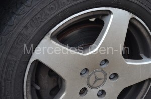
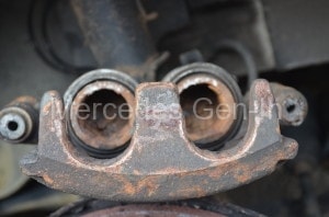
If the ‘chuffing’ has been noticed early on, none or very few ‘black death’ carbon deposits will be seen, just wetness from ejected diesel resulting from the failing combustion process forced up around the leaking injector out to atmosphere on the cylinder head.  If carbon deposits are present then they will have to be completely cleared and chipped away with a blunt screwdriver/scraper and vacuumed away as you go.

Injector Black Death Mercedes Sprinter

Injector Black Death Mercedes Sprinter

Because of the close proximity of other injectors it may be difficult to identify exactly which one is the culprit.  If the leaking injector is not obvious, then clean down the area with Gunk or other degreaser and dry off the area (engine off of course) completely.  Using 2 inch strips of old brown paper cut from the envelopes of your unpaid bills (joke) make hollow tubes and wrap them around the injectors, fastening the ends together with a paper clip. Do this for all suspect injectors.  Start the engine and watch for the darkening/spotting of the brown paper with diesel spray, this will indicate quite clearly where the problem lies.

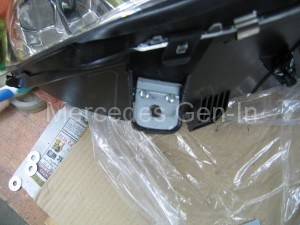
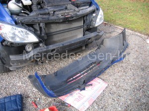
Once identified the work can begin – Run the engine until nice and warm then turn it off and remove the keys.  Remove the turbo supply hose to the inlet manifold and split the composite intake manifold by removing the pins that secure it to the lower section.  Remove the two pins that are also fastened to engine brackets at the rear and front of the head by the fuel filter.  Lift off the manifold and stuff the remaining open ports with paper/cloth to prevent bits dropping inside.  Check the gasket at the back plate/cover of the upper section of the inlet manifold as this is prone to squeezing out causing turbo boost leak and is this a good time to take a look/plan to rectify.

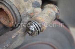
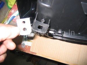
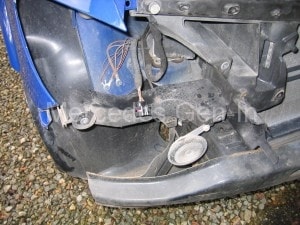
Remove completely the steel fuel supply pipe from between the leaking injector and the fuel rail along with its injector electrical connector; tie this cable out of the way of the work area.  Remove the long single 6mm torx bolt that secures the injector clamp and place it safely to one side with the clamp itself.  Inspect the threaded portion of the 6mm bolt if it is damaged or showing heavy signs of alloy material deposited on the threads then further action may be needed later on to rectify the threads in this failing all important tapped hole.

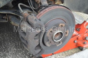
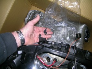
The next part of the procedure is ‘make or break’ for the DIY repair and is the point of no return so please take heed.  Try to rotate the unclamped injector, if it moves freely by hand then great, if it won’t budge try a little more force – but not too much.  If it’s seized then at this point re-assemble the engine and take it to a diesel specialist as damage to the injector or head can be very expensive indeed and botched repairs will easily exceed the cost of it being done by a professional in the first place – you have been advised.  If the injector rotates, begin to pull it upwards whilst twisting the body, if it jams, twist it the other way and work it using some penetrant or WD40 in the area around where it enters the head.  In some cases the injector lifts out instantly, in others it can take hours of wiggling and fiddling, don’t be tempted to use hammers or heavy tools to do this job as commonly expensive damage results.  The image below shows damage to a rocker/cam cover caused by levering against it to extract a stubborn injector.

Damaged Sprinter Rocker Cover

Damaged Sprinter Rocker Cover

Once the injector is out, clean it off and place it safely out of the way then recover the single copper washer from the hole in the head that forms a gas tight seal for the injector against the aluminium cylinder head.  Use a torch to inspect the injector seat in the cylinder head, it will likely be blackened and carbonised, this needs to be cleaned off and in severe cases re-cut to present a perfect sealing surface.  I have in the past had great success using a wooden dowel, rather like the ones used on a valve grinding hand tool.  Using contact adhesive stick a square of medium abrasive paper to the end of a flush cut dowel, allow the glue to dry then trim round with scissors.  Pop this tool down the hole and clean the seat as if you were grinding in a valve.  Inspect it regularly and if there are slightly deeper grooves remaining keep going with new paper until clean and flat.  Now the top tip, it will be necessary to purchase a new copper sealing washer.  The best thing to do here is purchase a Honda part in preference to the genuine Mercedes Benz item.  This washer is the standard CDI injector seal used on all modern Honda 2.2 litre diesel engines (More info on the Honda seal – here).  I personally have had great success using the Honda part as they seem to be made from a superior material and appear more compressible thus making a better seal against any slight face imperfections.

Sprinter Injector Seal

Sprinter Injector Seal

If your 6mm torx clamp bolt came away cleanly and without damage, discard the old one and purchase a new item from Mercedes.  This part is a stretch type bolt and once used must be replaced.  The bolt hole has to be spotless and clean and have no debris or metal swarf at its base.  Any solids in the hole will be compressed at the base of the drilling when the bolt is tightened and can cause cracking or worse – bursting through into the water jacket of the cylinder head (really easily done) so clean that hole with an air-line or blow gun until you are sure it’s clear.

Sprinter Diesel Injector

Sprinter Diesel Injector

Replace the injector with its new copper sealing washer, using a slight smearing of high temperature ceramic grease on the body sides and position it correctly with regard the electrical connector, replace the clamp and clamp bolt, fit the new clamp bolt and torque it down to 7Nm then 90 degrees turn to finish – NO MORE.

While the actual MB recommended spec for tightening the hold down clamp bolt is 7Nm plus 90 degrees, plus 90 degrees – 7Nm plus 90 degrees will provide a safer torque to yield on a new bolt in an old head.
The Honda washers are ‘softer’ (unmeasured science, but you can tell) and I have always consciously never bothered with the extra and last 90 degrees crank. Never had any trouble.

Each 90 degree rotation past 7 Nm with a new clamp bolt and clean hole results in a further 0.3mm stretch bolt yield, so my view has always been – softer composition, less crush and a little less beads of sweat on the final swing of the wrench! (Those threads are a weakness) Correct spec by the book with thinner less malleable copper MB washers is 7Nm +90 +90.

The full factual reference write up is here, I always have agreed with the final conclusion that offers this advice and hence never added the increased stress of the final 90 degrees. Obviously the final choice of wether to use the factory torque spec or the modified spec is entirely your choice, but the tests carried out below are well worth a read before you make that decision.

Technical Reference Article:-

Tightening the fresh hold down bolt and seal ring will produce the same clamping force (defined by seal ring crush thickness) regardless of which of the 2 torque specs are used.

The desired residual bolt stress (to achieve essentially infinite cyclical fatigue life) is achieved by both specs but the 2X 90 spec does allow for less care and precision during the tightening procedure. Torque spec #1 (62in/lbs +90) is certainly less risky if contamination may be lurking at the bottom of the very deep blind bolt hole. I suspect it is also somewhat less risky if the aluminum threads are not in ‘as new’ condition.

“Here at the Global Sprinter Research Center I am always eager to investigate Sprinter related technical issues.

Group members have noticed that Mercedes Benz has a published torque spec for the injector hold down bolts that seemingly differs significantly from the long standing DC published specs as shown in DC workshop manuals as well as on the instruction sheets that DC at one time included with replacement injectors. The extended threaded shank length, 85.83mm long, 6.0mm dia., 8.8 grade, factory hold down bolt, hold down pawl and injector seal ring are identical part numbers for both the 5 cyl. and 6 cyl. engines.

Using my ‘test’ 647 Sprinter cylinder head, which is permanently mounted to one of my work benches, I have recently performed tests related to hold down bolt torque. This dedicated ‘test’ cyl head has been quite useful in my repair tooling fabrication.

As many of you know I have developed in-house tools and fixtures for removal of broken hold down bolts, repair to stronger than new stripped hold down threads, and various custom black death repair tools for my in-house use. This test head features my custom carbon steel hold down threads making it ideal for these hold down bolt torque experiments because data is not compromised by any aluminum thread deformation or failure.

After careful measuring of bolt length (before and after torquing) and injector seat seal thickness to 0.01mm tolerance, and using a calibrated Snap-on electronic 1/4 inch drive torque wrench set to display in/lbs and accurate to 0.1 in/lbs, I have the following observations to report:

TRIAL 1– A fresh, factory hold down bolt torqued to 62 in/lbs (approx 7 Nm) and then an additional 90 degrees, results in 0.08mm crush of a fresh factory seal ring.

The Sprinter’s copper seat seal ring features a double convex cross section and the clamping force induced ‘crush’ creates narrow sealing flats on each side of the ring.

Monitoring the bolt torque during the 90 degree rotation reveals a peak of 180-190 in/lbs before full 90 degrees is achieved and remains at this level all the way to 90 degrees. This peak/plateau signals bolt yield has occurred.

TRIAL 2– A new seal ring and a fresh, factory hold down bolt torqued to 62 in/lbs. (approx. 7Nm) and then an additional 90 degrees X2 (FULL 180 degrees), results in the same 0.08mm crush of the seal ring as well as a steady 180-190 in/lbs torque reading during angle tightening.

Being a stretch to yield, non-reuse, bolt it was not surprising to see permanent elongation. Elongation was approx. 0.30mm for each increment of 90 degrees of tightening rotation (after the 62 in/lb initial torque).

TRIAL 3-A fresh hold down bolt tightened to failure. The bolt tolerated several additional 90 degree sequences PAST the initial 62 in/lbs and 2×90 degrees.

It has previously been reported that fresh hold down bolts have failed when several group members had torqued to 62 in/lbs and then 180 degrees (mistaking 1/2 turn for 90 degrees). I now suspect this occurred because of bolt bottoming in the base of the blind bore. Bottoming can occur because of debris at bottom of the blind hole.

CONCLUSION:

Tightening the fresh hold down bolt and seal ring will produce the same clamping force (defined by seal ring crush thickness) regardless of which of the 2 torque specs are used. The desired residual bolt stress (to achieve essentially infinite cyclical fatigue life) is achieved by both specs but the 2X 90 spec does allow for less care and precision during the tightening procedure.

Torque spec #1 (62in/lbs +90) is certainly less risky if contamination may be lurking at the bottom of the very deep blind bolt hole. I suspect it is also somewhat less risky if the aluminum threads are not in ‘as new’ condition.

Be sure you test your cyl head’s bolt hole threads by using a wire brushed used hold down bolt with an indexing paint mark, turning in by hand while counting turns, to assure threads are clean and bore is unobstructed to full depth.  This is especially critical when performing black death surgery.” 

Information source provided with thanks by Andy Bittenbinder 

If you had a problem with the thread you can use this type of kit or as a more desperate measure carefully tap out the hole to 8mm using a long series drill and tap, if you do this you will also have to drill out the clamp bracket to accept the new diameter bolt.  When drilling/tapping take care to not descend deeper in the head than you need to and break into the water jacket.  Sometimes you may find that the previous repairer has broken into the water jacket – add a small amount of silicon gasket compound to the last section of threads of the pin and tighten down in the normal way.  This is not the best way to get out of trouble, but will at least enable you to complete the job.  If you don’t do this and a bolt hole is broken through – you will leak water!!

Now your injector is back together, in the cylinder head and clamped down, reconnect the steel fuel supply hose and electrical connector and build up the inlet manifold and turbo pipework.  Start and test the engine.  The engine should fire after a couple of cranks as no fuel bleeding is necessary.  All should now be well with the repair and you have carried out a major maintenance repair saving you hopefully quite a lump of cash.

More info dealing with the actual removal/installation of the injector and its seal – here

Good luck.

Improving the Mercedes Vito W639 Horn


If you own a late model Mercedes Vito 2004-on (W639) you will no doubt be fully aware of how poor the horn is compared to other medium sized commercial vehicles and most other cars on the road!.


Vito Horn

Original Single Horn Vito W639


This can be easily remedied by installing better horn sounders – a trip to the local scrap yard will produce the goods at a very low price.  Sure, you can buy off-the-shelf horns from accessory shops but rarely are they of the quality of OEM units, often made by top manufacturers like Klaxon, Hella or Fiamm.  When you get to the scrap yard look for high end saloons and estates, BMW, Jaguar and Audi being the most common producers of quality dual horns.  Always identify the ‘scroll type’ horns in preference to the feeble disc horns that are common these days, look for good clean examples, there will be plenty to choose from.  The scroll type horn produces a loud and full tone, a Hi-Lo tone pair will when fitted, scare most motoring offenders out of play!


Replacement Mercedes Vito Twin Horns

Fix upgrade twin horns behind grille

mercedes Hi Lo Twin Horns

Drivers side horn mounting location


I secured my pair of horns from a BMW 5 series, manufactured by Klaxon and both very clean indeed, they cost £5 for the pair and I would imagine cost in the region of £70-£80 off the shelf.  I cut the wiring looms back as far as possible when removing them from the donor car so that I could fully utilise the attached wiring and their waterproof plug and socket type power connectors.


Mercedes Vito Twin Horn Upgrade

Twin Horn Mounting location behind grille


Fitting was easy.  Lift the bonnet, remove the three screws on the top of the grille, un-slot it and remove it up and out from the Vito. Locate the two plastic moulded grey ABS brackets either side of the radiator that support the front bumper skin, position your horn on the inside of these brackets and check the fit.  Drill a suitable hole through the plastic bracket and fix the horns either side – note there is a great deal of room behind the grille if its a model without air conditioning.  You will probably have to be a little more inventive with the mounting location if you are restricted by the air-conditioning condenser and its cooling fans, it would probably be good practice to check clearance by refitting the grille before committing to a mounting place.  However it is an easy job to mount the horns in this area.


Mercedes Vito W639 Horn Location

Mercedes Vito W639 Horn Location


Once you have mounted the new horns, wire them both in parallel and route the two connecting wires through to the drivers side headlamp unit (Right Hand Drive). Stretch your arm down behind and below the headlamp unit and you will find the original single disc type horn, feel for the connector and unplug the lead feeding it back through to the engine compartment.  Splice in your new horn wires to the original horn connector, tape up the joints and tie wrap the cables neatly out of the way.  Test your horns and refit the grille assembly.  If you would like to hear the resulting sound of fitting the dual tone horns, just select the W639 horn sound track in the Mercedes Sounds player to your right and click play.

Twin Horn Upgrade Mercedes Vito W639

New twin horns hidden behind grille

Job Done !