Technical E Class W210

Technical E Class W210

Philips H1 Auto Bulb Corrosion Problem – Mercedes E Class W210 Fog Lamps


No under bumper lamps and the dashboard bulb failiure indicator pointed to the fact there was an issue with the fog lamp bulbs on the E Class W210.  When the weather improved enough to investigate I had a peek at the problem.  As you may know, access to the lower fog lamps rear casing is very restricted without raising the car on a jack, this was the reason I had not tackled the problem until it had at least stopped snowing!

Mercedes W210 E Class H1 Bulb Problem

Both lamps had failed, but not blown filaments!

A small hinge-down flap, forward of the front wheels in the plastic under-skirt  is undone by slotting a 50p coin into and rotating the catches (two on each flap), once open this gives access to the rear of the fog lamps.  The lamp housing is opened by releasing the single plastic catch at the bottom of the assembly and levering the rear lid outwards then down – out of two locating slots on its top edge.  There is a standard spring-arm retainer holding the H1 lamp in place, once released the bulb can be withdrawn and the single spade electrical connector removed.  Replacement is a reversal of the removal.

Philips H1 auto bulb corrosion

The bulb itself was in perfect condition, but the welded connection between the filament and holder body had corroded causing an open circuit.

On removal and inspection the interesting thing that I noticed was the bulbs themselves had not ‘blown’ their filaments, but had corroded in an identified weak spot on the filament connection where it joins to the fabricated steel holder. The fact that this was common to both left and right lamps with the same corrosion, pointed towards a possible issue with the termination welds on Philips H1 type bulbs.  If you look at the photograph below you will see a yellow sulfurous corrosion that has eaten through and separated the spot weld that attaches the filament wire to the metal support (earth) body of the H1 lamp.  When it was cleaned away with a sharp pointed knife it could be seen that the corrosion had totally separated the once welded filament wire from the support post creating an open circuit.

Philips H1 auto bulb corrosion close-up

Corrosion had allowed the filament tail spot-weld to part from the lamp holder body.

As this had happened in an identical way on both bulbs I suspect a manufacturing fault or a selection of dissimilar metals that have some galvanic action causing this corrosion.  Either way it was the failiure of the lamp bulb construction rather than the filament that caused the open circuit in both cases.  I replaced my lamps with Osram H1 bulbs which have a better more robust filament connection arrangement and will now use this manufacturer in preference to Philips !  Make your own mind up !

Osram automotive bulb data : Osram data sheet link.

Philips Auto-bulb corrosion problem

Corrosion has caused the separation of the terminal and filament.

W211 Wheels on W210 E Class – Do they fit ?

I have read a great deal of debate and mis-information about fitting later W211 E Class genuine MB wheels to the W210 E Class, I would like to think that this is the definative answer to this often asked question.

As a generalisation the wheels will fit, with a couple of important proviso’s.  The first is that although the PCD and hub centre diameter are exactly the same for both wheel series, the fixing studs and their associated stud ‘dome’ diameters are different and to do the job in safety a special set of wheel studs needs to be obtained and fitted. The dome on the stud nut seats snugly with the radius seat machined into the alloy wheel casting this allows a large contact surface area for load bearing and facilitates correct centrering enabling the mount of the wheel securely to the hub

The original W210 wheel fixing used a M12 wheel stud (lug-nut) and the later W211 uses a M14 wheel stud, both of the same style but with different radius seats and are as such incompatible. (M12 stud has 12mm radius seat and M14 stud has 14mm radius seat)  You will have to get a customised set of studs that have an M12 threaded portion but with the M14 type radius seat to correctly mount these wheels.  You will need to purchase a set of wheel studs like these  http://www.alloywheelsdirect.net/option/bolt_packs    BOLT PACK 4.

The wheel and tyre combination should be fine with all models with the note that Avantgarde models that have lower suspension, be prepared to reduce the tyre width if there is any foulling.  I have the Elegance model of the E320 CDI W210 and the W211 ‘Yilduz’ wheel –  7.5Jx16  –  fits perfectly with 235 55 16 tyres (the widest profile MB specify for this for wheel on the W211)

The ET offset values of the older W210 is ET38 and the later W211 is ET42.  Clearly the few mm difference in the ET allows fitment of the later genuine wheel without fowling of the rim but if you decide to use non-mercedes aftermarket wheels observe caution and aim to get wheels with an ET offset at least within the above range. (ET38-42)

They look nice on the car and I think its well worth the effort!

wpid-20130102_092208.jpg

Mercedes SRS Fault – Fix

Here is a way to deal with a common SRS fault that lies within the seat pad of the Mercedes E Class (W210). (I am sure also similar for other models)
The service history of my current E Class W210 shows repeat visits over 10 years for this specific SRS problem and I would like to share with you the ins and outs of it all (each visit cost the previous owner £220 for the cure/pleasure – only to have it return again almost every 18 months to 2 years during ownership)
If the red SRS lamp on the dash is accompanied by the orange airbag lamp next to the transmission shifter is lit, the fault is commonly connected to the passenger seat sensor. As I imagined the previous owner had always a rather ‘cuddly’ passenger riding shotgun, the seat would have taken a pounding, the flopping into the car was probably the most damaging to the seat related parts I am about to describe.
HOW IT WORKS
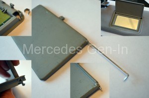
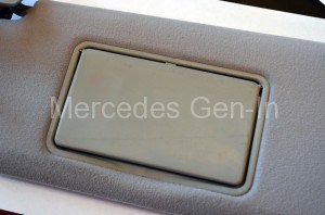
Layered within the seat base skin of the passenger seat, there is a complex contact matrix (like a foil printed circuit – looks like an aerial view of a maze) that senses if the seat is occupied (a bum on it) and in most cases with post face-lift models, also auto-senses the proximity of the MB child seat. The former sensor circuit is used to switch off the passenger air bag if the seat is unoccupied, the latter is to used to switch off the passenger air bag when a MB child seat is fitted on the seat. Understanding that the weight may fool the occupancy sensor to thinking an adult bum is on the seat, the child seat detector overrides this and signals the Air Bag Control Module to turn off passenger side airbags. When it does this, the orange Air-Bag off transmission LED illuminates showing the system is disabled and its safe for baby to travel.
On cars pre face lift, without auto child seat detection, the connection from the seat occupancy sensor is connected directly to the Air Bag Control Module and operates just as a simple switch, changing the potential of the signal line to the module when sat on. Post face lift set up is far more complex. There is an electronic box inside the seat base that forms part of the sensor matrix, the ends of the wire ‘maze’ are connected to this and it converts the status of the occupancy detector into a CAN output signal that is piped to the Air Bag Control Module (as a PWM signal) An over simplistic way to imagine this, is to think of it as a pulse, like a heart beat at a fixed rate. This beat is detected by the ABCM (Air bag control module) when the seat is unoccupied and turns off the air bags on passenger side. Once the seat is sat on, the electronic box in the seat changes the frequency of the pulse which is again detected by the ABCM to turn the passenger bags on. The other function of the electronic box within the seat is to auto-detect the presence of the MB child seat, this is done by using RFID (radio frequency identification) working in the same way as the detection alarms at the doors of music shops etc. The RFID token hidden in the child seat is detected by the seat matrix (antenna) and the electronic box then gives out the all important seat unoccupied/child seat in place PWM CAN signal to the ABCM turning off the passenger bags and illuminating the advisory air bag off light.
HOW TO FIX IT
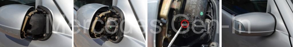
There is a yellow connector beneath the seat, this houses all the connections to the seat pad sensor and links its signals to the ABCM. It is very common for the wires to and around this connector to break (seat-side) as they are very fine conductors indeed and this is compounded by a slight design flaw, in that the cable that enters the seat base to the matrix is tie-wrapped to a metal seat component which in turn causes a stress fracture along the wire length where fixed. So the first thing to check is the connector and it wires (best to remove the seat) If the break is suspected within the depths of the seat base, then it has to be stripped to repair/replace the parts. (This is where the repeat £220 bill from the agents came from!)
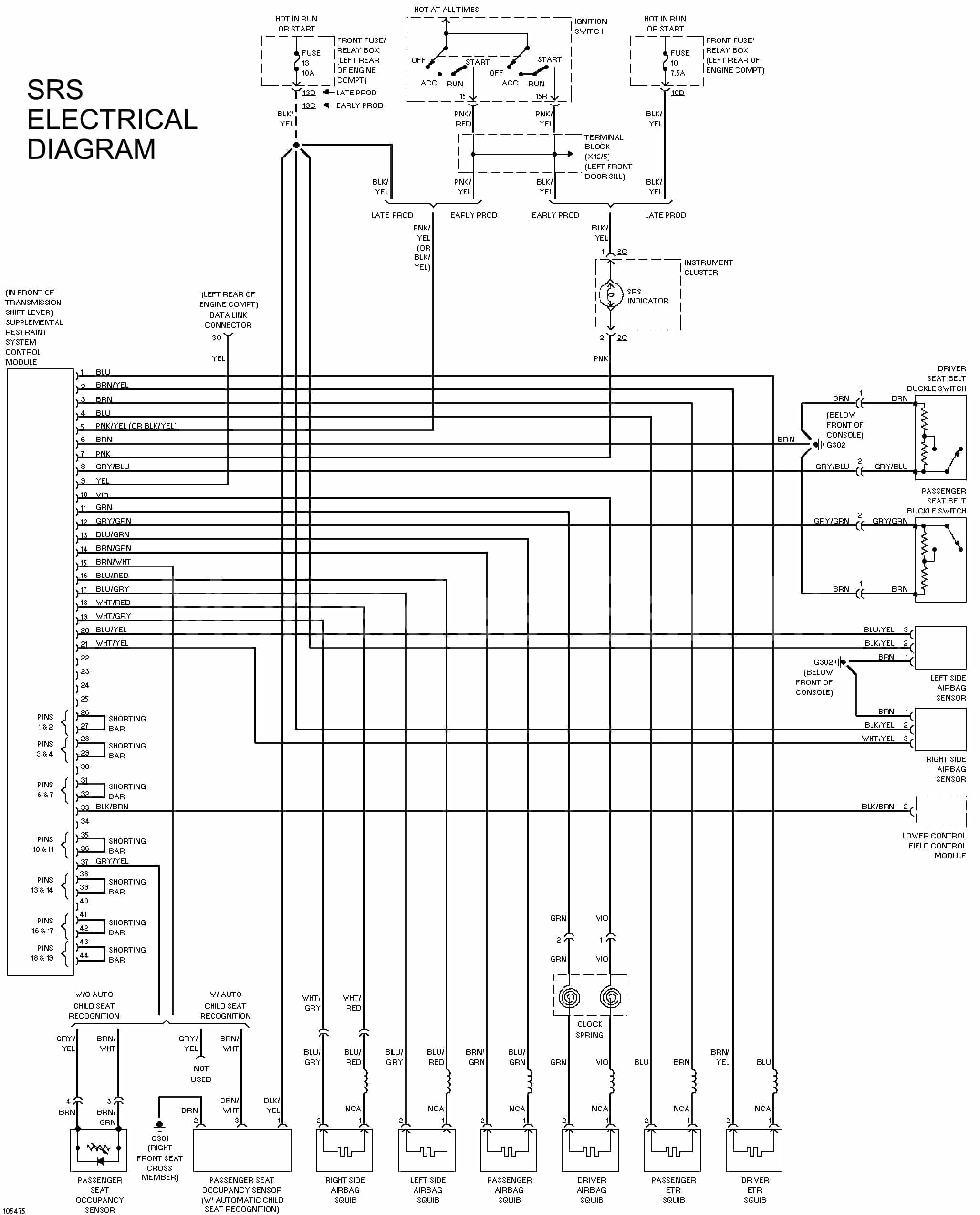
Understanding that this is a life saving safety system and the owner may wish to entrust the correct remedial work to a dealer or do it himself with the correct MB parts, there exists however ways to get around this common failure, it is up to you as a reader/owner to make up your own mind if you wish to follow and act on this information. I would not recommend that any of the following solutions be used if the vehicle is or could be used carrying young infants in the front seat, but worth considering if you are grey and old (past it) like me. I have attached a useful wiring diagram of the SRS components so you can identify what’s what on the connector etc. But if you can’t fathom the circuit, then my polite advice to you would be to not mess any further!
So you are still with me…
If your car is a pre face lift, with a non auto detect child seat, then the seat pad matrix can be simply linked out on the yellow connector under the seat. This will signal to the system that someone is sitting in the seat all the time and cause the passenger airbag to be permanently ‘live’ whether anyone is sitting in the seat or not! (In my view better than not working at all) This is a great fault finding tip if nothing else, as it proves if the fault lies within the seat pad, as the SRS lamp and air-bag orange lamp on the transmission will extinguish immediately the ignition is turned on (without a star reset!)
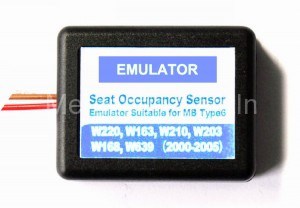
A later auto child seat detecting, post face lift, later  E Class W210 model, cannot be ‘linked out’ in any way sorry!  It needs a CAN keep alive signal to the ABCM to signify that the system is fault free (default seat unoccupied signal) so any fault occurring in the wiring or seat matrix resulting in the PWM output failing will deny the function of the passenger airbag by default and raise the SRS dash lamp along with the orange air bag transmission mounted indicator. So strip out the seat and remove the leather etc etc…… OR buy a magic box from China from the large online auction sites. This seat sensor emulator box, usually around £15 delivered to your door, provides a seat occupied PWM signal output that once connected, fools the ABCM into thinking all is well and that there is a bum on the passenger seat. There are 3 wires to connect, colour for colour those that exist under the seat Brown, White and Red on the yellow connector. This resets the SRS lights as before on ignition power, without a star reset.
Just for information the China emulator box contains a programmable PIC chip that emulates exactly the signal that would be given from the MB seat pad matrix. Make sure you get the correct one for your correct model if ordering, as there are a couple of types of ABCM used through model years.
emulator
So hopefully this has been useful in explaining how the SRS seat sensor system works and that from this you can get an idea what is ahead of you. I tried to find out information like this and its a little sketchy and hard to place so maybe its of some use in your fault finding, diagnostics and resulting repair. The diagram below is especially useful !
SRS Electrical Diagram:
Print

Mercedes Vanity Mirror Flap Broken – Fix

Vanity Mirror Flap Repair

Out of the two W210 E class Mercedes I have owned the flap that covers the vanity mirror on the sun visor has been broken. Also a friend’s C Class had the same issue so maybe it’s a more common problem than I first thought!

Any way auction site/breakers prices start from about £20 for a used grubby part with the shipping, if you wish to take a gamble on it arriving in the same trim colour – so I fathomed a cheap and quick repair that works very well and costs almost nothing but about half an hour of time at
the most.

First remove the 2 screws from the headlining on the visor hinge and take out the visor.

Using a blunt knife from the kitchen drawer, prise out the mirror frame from the visor. Work from the bottom edge, away from the hinge side first.

Find some stiff steel wire about 1.5mm diameter and cut two 4 inch long pieces.

Cut off the existing moulded hinge pivots from the mirror cover flap, at least one should be broken off anyway!

Heat the end of one piece of the 1.5mm wire with a flame (lighter) until its cherry red.

Push the heated wire into the centre of the hinge pivot point in the mirror cover flap, repeat a few times until you get a depth of about 5 or 6mm into the moulding then let it cool fully, it will now be fixed into the plastic as the new hinge.

Cut the material away from the side of the frame to allow the new wire hinge pin to pass through the original hinge receptacle and rest flat on the back of the mirror frame. Part assemble and then clip off the excess wire length with cutters.

mirror flap repair completed visor mirror flap repair

Repeat the process on the other side of the cover flap but assemble the flap into the frame before pushing the hot wire into the plastic
for the final time – let it cool, blowing on it speeds things up, then when fixed clip off this side with cutters too.

You now have a robust hinge that will last for years, it won’t break as it rests completely behind the plastic frame bezel .

To ease the process you may find it beneficial to remove the two spring bearers that apply pressure to the flap to prevent it closing in use, these can be simply refitted on reassembly.

Snap back in the mirror assembly to the visor, making sure the micro-switch is positioned correctly for the illumination lamp if your model has this.

Refit and admire your work.

Mercedes Slow Folding Electric Wing Mirror – Cure

Slow Folding Wing Mirror Fix

The driver’s side folding mirror on the
facelift E Class W210 cranked in at a painfully slow rate, seemingly if at all sometimes – so investigation was needed. Hardened grease was most certainly the cause due to age petrified grease in the folding mirror drive gearbox. (anyone who has ever taken an old wiper gearbox, or electric drill to pieces will know exactly what I mean!)

What to do:

Power the mirror in and assist it by hand if it’s really struggling, then remove the wing mirror cover (Fold the mirror in and release the square spring steel holding clip with a careful poke down the back edge with a screwdriver) Once free from the retaining clip, power the mirror to its normal position.  The cover now pulls away from the hinge part in the direction away from the car and hangs just far enough out of the way to proceed. Removing the outer cover reveals a second flimsy black plastic cover at the hinge point protecting the fold motor and gear assembly from the elements. Remove this cover by simply prying gently at its retained edge whilst pulling outward. Once this second cover is out of the way, the motor and gear quadrant is revealed.

Take a small sharp bladed terminal screwdriver and find the indicated location shown in the picture and make a small hole in the gear case just beneath the motor (push and rotate the driver a few times to make a neat hole, go steady though, the plastic is thin) Do not use a drill (hand drill or otherwise)as past disasters have shown how easy it is for the drill bit flutes to bite in the thin plastic driving the bit forward uncontollably into whatever you were carefully trying to preserve. Using the sharp screw driver method, although crude does gives a great deal more control of whats going on. You have been warned !

E class Mirror Fix

Protect the cars paint beneath the mirror with a rag and spray copious amounts of WD40 into the gear housing through your new hole, flooding the mech. Work the mirror in and out under power a few times, being careful not to trap the mirror cover that will be hanging loose.

Repeat the WD application and let it stand a few mins to soften the hardened grease that is the root cause of the issue. (Infact – go make a brew)

Give it a final spray with WD and run the mirror in and out several times, you will have noticed the fold speed increase almost immediately the first squirt got to work. Once you are happy with the fix, wipe off any excess and clean the plastic gear housing with de-greaser or such and put a small blob of silicone sealant over the hole you made. Reassemble and be very pleased with yourself!.

If you don’t make a cup of tea, this can be done half an hour a side easy.

Special note:

If your mirror cover has LED repeaters in the housing, clean up the connector pins before you re-assemble, as they will be corroded slightly and probably not contact correctly once the mirror cover is refitted. (I know this!) To facilitate easier location of the LED connector on reassembly, tilt the mirror glass down slightly, this gives you some clearance between the mirror cover and mirror itself to guide the connector home.