Technical MB General

Technical non-specific MB

Skipping Mercedes 6 Disc CD Changer – Work-around Fix


The older type of CD Changers fitted to vehicles that are ten to fifteen years young, if still in situ, are running on borrowed time. Complex electromechanical systems and solid state LASERs don’t have an infinite life and often replacing the unit with a more modern radio/cd or MP3 player is the best choice.  However for those of us with older integrated COMAND systems that use a dedicated cut out in the dash, it is not always practical to change the head unit to a more modern type without huge expense and if we want to play CDs the remote changer has to work as the slot up front is for the NAV disc only.

Mercedes Benz CD Changer Repair Work-around 8

So what do we do then…  The option is to source a used unit from a scrap car or breaker but it is most probably from the same era and will most likely be well on its way to end of life.  So if you have an issue of ‘Magazine Empty’ or a badly skipping CD changer then there is a couple of last things to try before lifting the lid on the recycling bin and dropping it in!

As the LASER ages it becomes less powerful, rather like a halogen bulb that yellows and gives off a degraded level of illumination to that it did when new.  What we can do is increase the current to the laser slightly to lift its light output to compensate for its ageing and hopefully put the player back into service for a while longer. (please note that by increasing the LASER current over the specified factory set optimum, will have the effect of shortening its life, but my view is – if the player does not work correctly now because of a poorly performing aged LASER reader, then it clearly can only really be fixed by replacing it – a cost option that usually outweighs the purchase of a complete replacement player.)

Mercedes Benz CD Changer Repair Work-around 7

Obviously it goes without saying that it may just be dirt that is hampering the function of the CD player and in a few cases cleaning of the LASER lens will rectify the problem. This is the thing to try first before making any electrical adjustment. You can use one of the specialist cleaning CDs you can buy with a fine brush attached to the playing surface.  As this is drawn into the disc changer and played, the fine brushes gently sweep dirt and dust particles from the lens at very high speed.  More stubborn dirt will have to be removed with the delicate use of a cotton bud and surgical alcohol.

Mercedes Benz CD Changer Repair Work-around 6

Assuming that you wish to proceed with trying to breathe a new lease of life into your old disc changer, and that you are not too bothered by the chance of failure – then read on.

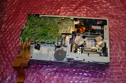
Eject the CD cartridge from the mechanism, disconnect the cables and orange DB2 fibre connection removing the player from its bracket in the car.  Working on a table or bench, unscrew the four cross-head screws from the sides and three from the back of the unit case, two of these hold the fibre convertor.  This then slots off sideways and the orange ribbon can be disconnected from the PCB connector by simply sliding out the white plastic anchor section about 2mm, releasing the foil from the PCB.  Now completely lift off the cover.

Mercedes Benz CD Changer Repair Work-around 5

Unhook the spring loading mechanism from each side of the unit, noting the position of the levers before doing so. These are set depending on your player installation – either Horizontal or Vertical.  Now pull off the four ‘gel’ shock dampers from the retaining spikes on the inner chassis (2 on each side) and undo a single retaining philips screw on the connecting orange foil assembly.  The inner chassis should now pull free from the base section.

Mercedes Benz CD Changer Repair Work-around 3

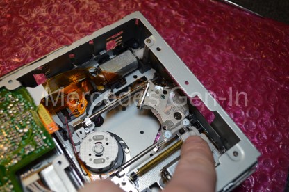
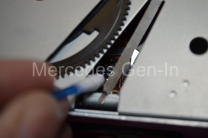
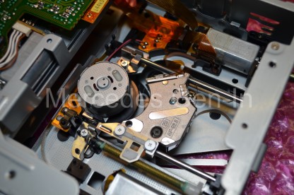
Identify the laser saddle and turn the lead-screw cogs with your finger to drive the LASER to the outer edge of the chassis, once in position turn over the player and you should be able to see the floating lens assembly through a gap in the mechanism top plate, there is enough room here to slide in a cotton bud and lightly brush the lens clean.  Use alcohol if any deposits are stubborn or difficult to remove, dry thoroughly and polish off any residue lightly with a dry cotton bud.  You may wish to try the player to gauge any improvement at this point, before moving on to the ‘last stand’ of adjusting the LASER current to get that last bit of life out of the player.

Mercedes Benz CD Changer Repair Work-around 2

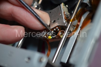
Go back to the lead-screw and run the LASER to its most inward position in the chassis and then look on the revealed vertical edge of the saddle and you should see a small ceramic trimmer or potentiometer, about 3 mm in diameter.  This adjusts the LASER current. On Older wired and DB2 Mercedes and BMW, Alpine and Becker changers – current is increased by rotating this tiny trimmer anti-clockwise.  It only needs to be moved by a small amount, as a small increment is often all that is needed to restore the player to a working state that may last for a good period of time, maybe year or even more depending on your luck!  Remember the LASER is probably problematic anyway due to its age, so by increasing the current you are stressing it beyond its designed limits – but if you win a year or more use out of it before the inevitable replacement of the changer – whats to lose!  Rotate the trimmer about 30 degrees anticlockwise and rebuild the unit and test.  More often than not this is all that is needed to get things running again.

Mercedes Benz CD Changer Repair Work-around 1

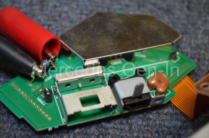
If you need to apply power to the CD changer while on the bench, dismantle the fibre converter housing and attach 12v DC supply as shown across the power diode on the PCB

Good luck! Remember this is not a repair, it is hopefully a ‘get-out-of-jail card’ used to squeeze the possibility of a little more operating time from a unit that is eventually going to fail.  Usual disclaimers apply, you do this modification totally at your own risk under the full understanding that it may not work for you and that it could backfire and you end up junking your classic player.


Mercedes Headlamp Adjustment Repair – Most Models


Here is a quick fix that will restore your failing or ‘wobbly’ headlamp back to a working condition.  If you notice that the headlamp leveller is not working correctly and on inspection the internal reflector seems loose and ‘disconnected’ from the lamp body – it probably is!  Caused by the internal ball and socket arrangements breaking that secure the reflector to the adjustment threaded rods.

If you are lucky the ball and socket arrangement will have just popped out and you should be able to snap them back in place once you can see exactly what you are doing.  The best policy is to remove the lamp unit and work on it at the bench or table.

Usually there is only two or three fixings that hold the lamp into the vehicle body and removal is in many cases quite simple (At least on the R170 SLK we have here)

Mercedes Headlamp Repair 1

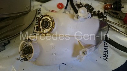
On removing the bulb access panel you should be able to see the issue.  There are three attachment points to the reflector, looking from the back of the right hand lamp there is a ball and socket on the vacuum leveller adjuster (could be electric in some models) to the lower left and two points of attachment top and bottom on the right, these are usually a cream/white nylon part, the socket of which is screwed to the rear of the reflector.  Its worth noting that if when you shake the lamp you can hear broken parts inside there is likelihood that one of the sockets has become brittle and broken.  As far as I know, even though these small plastic socket parts look to be replaceable, I have yet find a source. It would mean in most cases a replacement lamp to rectify the fault, used or otherwise its an expensive fix for an otherwise serviceable lamp.

On the R170 SLK once the indicator unit has been removed, by slotting a screwdriver down the 10mm hole at the rear of the lamp body and flexing the latch access can be made to the steel spring clips that hold the polycarbonate lens to the grey lamp body. Once these clips have been removed the lens and body can be carefully levered apart.  The front chrome surrounding lamp trim simply pulls forward and allows full access to the reflector.

Note at this point that if you touch the shiny chrome reflector with your fingers it will mark, equally if you try and rub it with a cloth, even light polishing will damage the reflector.  I have found that using a fresh pair of vinyl un-powdered gloves prevents any handling marks and is a great aid to working with the reflector parts as it prevents any damage.

Mercedes Headlamp Repair 2


Once apart the reflector pivots can be inspected, it will be clear if just pushing the unit back together will be your fix or if further intervention will be needed if you spy broken or missing parts.  In the case of the SLK lamp, one of the nylon sockets had lost one of its three retaining ears allowing the ball to spring out of place very easily.  What was required was to retain the ball and push it into contact with the two remaining ears, giving a secure and durable mounting to the broken part.

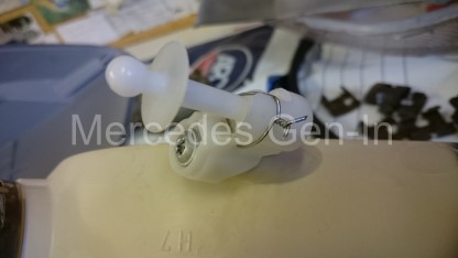
Taking a small jewellers screwdriver (app. 1mm diameter) heat it with a cigarette lighter and melt two small holes in the plastic socket, next to the point where it fixes to the reflector body with the single torx screw.  The hole position should be so that they are level with the top flat edge of the nylon ball once it is fitted to the socket.  Thread a paper clip through the two holes and enclose its free ends around the ball whilst holding everything tightly in place.  With pliers twist together the two ends, applying tension to the socket and bridging the paperclip diagonally across the top flat surface of the ball where the retaining ear is missing.

Reassemble the lamp, threading the repaired parts back together, pushing it home into the receiver of the vacuum or electrical adjuster.  If possible always move the sockets around so that the broken one ends up on the headlamp leveller as this can be snapped into place more easily on reassembly than the other attachment points.  Often the sockets are the same moulded part fitted to different points on the reflector and this allows them to be positioned so that any repaired socket is under the least supporting stress (leveller position).

Rebuild the lamp ensuring to use a light smear of clear sealer on the headlamp lens to body gasket if it looks to be leaking or allowing any dirt build up under the lens lip. Clip back all the lens fixings and refit the lamp to the vehicle.  Adjust the beam pattern to the specifications required by rotating either the up/down or left/right adjusters, be sure to make any adjustment with the instrument leveller control set to ‘0’.

Mercedes Sprinter Clutch Replacement (T1N, NCV3, VW Crafter and other MB)


Clutch replacement on any vehicle can be an expensive job, especially if you are entrusting the job to a main dealer.  Although large scale and a little mauling, clutch replacement on Mercedes models can be well within the capability of a competent DIY’er with only a limited number of tools.  In this post we shall look at the replacement of the clutch mechanism (including Dual Mass Flywheel DMF) on the Mercedes Sprinter – both older and newer models.
Mercedes Sprinter / Crafter Clutch replacement

There are several important details often overlooked about the Self Adjusting Clutch mechanism or SAC, that the installer has to be aware of so that things go smoothly.  You will no doubt have read many horror stories on the web of people installing SAC clutch units only to find that on re-assembly they have no functioning clutch, then having to take it all apart again to do it properly!  The first thing to understand is how the clutch actually self-adjusts over its life and in this understanding it will allow you to assemble things in the correct manner, so when you put that last bolt in place you are certain things will work as they were designed.  If you are fitting used components, such as a second hand DMF (flywheel) or even a complete used clutch, this knowledge is ever more important.  You would also additionally need to know how check this if you were stripping and replacing the original clutch and flywheel from an engine only to replace it later, say if you were replacing a leaking rear crank shaft seal for instance.

You will remember from days of old that clutches on older vehicles used to have a different bite point as they aged, either right at the bottom or top of stroke depending on design.  This is not the case today with advancements in clutch technology.  Mercedes clutches and other vehicles too, now have circular adjusting mechanisms built into the cover plate and spring that move to compensate as the clutch wears, maintaining the release spring pressure and finger position.  This means that as a SAC clutch ages, it maintains the same spring operating position and ensures a constant actuating force to engage/disengage the clutch over its life.  Indeed it is almost impossible to tell if a modern clutch is ‘new’ or only ‘weeks from failing’ by the pedal position and feel alone – all thanks to the SAC.

When you purchase a new clutch kit you will almost always find that the clutch has been ‘set’, and is ready for installation. However it is always best to check that things are correct before fitting as I have known due to rough handling even new cover plates ‘spring’ into a full adjustment position – clearly fitting this as-is would result most probably in a non functioning clutch.
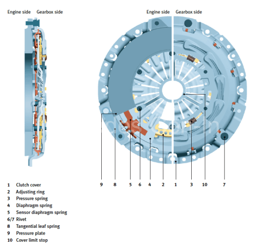
Mercedes SAC Clutch

From the illustration above you will see the cover plate/spring assembly has an adjustment ring. (2)  Simply put, this circular ring is allowed to rotate if required a few degrees when the diaphragm spring is fully compressed (when the clutch is operated) Its rotational resting position is controlled by the combined action of a sensor diaphragm spring (5) and the main diaphragm spring (4), allowing the plate to slide round slightly, facilitating changing the pivot point of the main clutch springs as the driven plate wears. There are three small springs that pre-load the adjusting ring so that as the clutch wears the adjustment ring is forced to rotate slightly to drive what is in effect a ‘wedge’ into the forming clearances of the cover plate diaphragm spring at its pivot point, thus allowing clearances to be ‘auto adjusted’ within the installed cover plate.  More information about the SAC from LUK if you wish to view here.

The adjustment ring’s spring position can be seen to be fully extended on this worn clutch cover plate below, the photograph below that shows the adjustment ring in ‘set’ position, this is how the clutch needs to look before fitment. Always check this before installing the cover plate, even if just out of the box!  There are many expensive tools used for correctly setting the adjustment of the pressure plate once installed on the vehicle, whilst these are great to own, unless you fit clutches every day it is hard to justify their purchase, this post outlines how it is possible to carry out this work without the special setting tools.
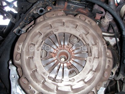
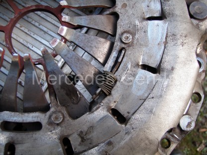
SAC cover plate showing adjustment ring spring positions for a worn clutch

Mercedes clutch SAC adjustment ring spring set position

If you are using a used clutch, or simply refitting your original plate, it is important to check or reset the adjustment ring to the ‘set’ position shown in the photograph directly above. This can be achieved in a press used between the stamped steel cover plate edges and the diaphragm springs.  If you do not have access to a means of compressing the diaphragm springs so that the adjustment ring can be counter rotated and reset, you may wish to read on, but use great care – as there is a fantastic amount of pressure behind those diaphragm spring fingers and a truly huge amount of force is needed to compress them!  The following is an emergency measure, only to be used to get you out of trouble and is definitely not by any means a recommendation.

On a solid driveway, place a hydraulic trolley jack under the rear axle of the vehicle and raise it enough to fit the cover plate, supported on three stout short wooden blocks of the same size, resting on the flange/outer lips of the stamped steel plate only, NOT the pressure plate (form the wooden blocks into a triangular formation).  Using a very large socket that will generously cover the hole in the centre of the diaphragm springs, align this with the axle beam or lower shock absorber mount – use solid wood packing as needed.  When in position bring down the jack ‘very slowly’ to allow the axle weight of the vehicle in controlled contact with the socket via the wooden packing, depressing fully the diaphragm spring, almost to the cover limit stop. (shown in cut away diagram above)  Now carefully rotate the adjustment ring anticlockwise with a stout screwdriver until it rests fully against its stop and the three small springs are fully compressed.  Once achieved, jack the vehicle once more and remove the cover plate that is now set for installation.  Throughout this procedure please consider your own safety at each step of the way!
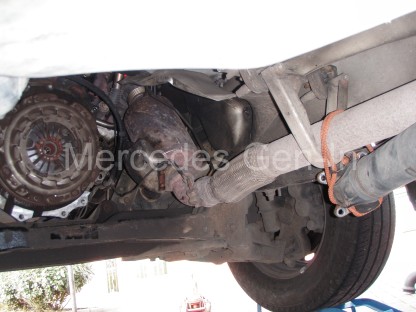
2005 Sprinter T1N Gearbox Removal

Now you can begin to remove the gearbox and fit your clutch.

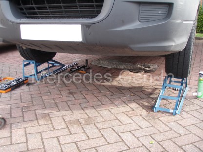
Working from ramps with additional additional 4-6 inch raising blocks if you have them, is the best way to achieve enough space to work comfortably around the gearbox, leaving yourself enough room to manoeuvre freely and eventually remove the gearbox from beneath the vehicle.  I always jack the vehicle onto ramps, this allows you to place one ramp forward and the other facing rearward, thus locking the vehicle from rolling either way to supplement the handbrake and rear wheel chocks.

Disconnect the battery before starting any work, as you will no doubt disturb the starter motor during the job. Also on later Sprinters,  W639 Vito and VW Crafter models remove the complete air box from under the bonnet, this prevents any strain on the plastic components, as the engine naturally tilts backwards when the gearbox support is removed.
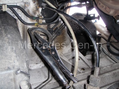
Sprinter hoses and gear cables held out of the way

Use a trolley jack to support the plate that supports the back of the gearbox near the output flange.  Undo all the bolts that hold the support plate to the chassis rails on either side, allow the jack to be lowered and removed. This will drop  the rear edge of the gearbox down a little so that the rear gearbox mounting pin can be removed and the support plate taken out from beneath the vehicle.

Using a 16mm socket remove the four propshaft flange bolts from the gearbox output shaft.  You will now have to remove the drop protection ‘horse-shoe’ brackets and the two centre bearing bolts to allow you to drop the prop sufficiently to allow you enough flex for it to be moved out of the working area to one side of the vehicle.
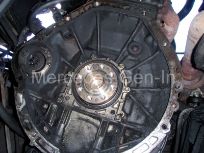
Sprinter with DMF removed

Now remove the gear selector cables, make sure you mark the shaft positions in the plastic ball-ends (amount of insertion) before you release them and tie them to one side. Put a latex glove under the cap of the brake/clutch shared master cylinder, before clamping off the flexible clutch hose from the chassis to gearbox. With a small screwdriver or pick, detach the hydraulic connection retainer clip from the gearbox hose coupling, keeping this in a safe place.  Pull out the hose and again tie it out of the way of the working area.  Remove any electrical connector or plug and tuck them out of harms way.

Now using at least a 24 inch extension bar and reverse torx socket remove all the ring bolts from the bell housing. There is no need to fully remove the starter motor, just let it rest in position.  It will be held in place by its thick cable. On T1N models up to 06, you will have to remove the exhaust support (2 x 12mm nuts) as this sits sandwiched directly behind the gearbox and will prevent removal unless fully removed.
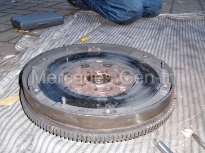
Sprinter DMF Flywheel removed

When you get to the last bell housing bolt, support the gearbox centre on the hydraulic jack, remove the final bolt. From the back of the gearbox pull, the casting should now separate from the engine block.  Manoeuvre the gearbox back and lower the jack. Take the gearbox from under the vehicle.  This is a great time to check for leaks or damage/wear to the selector mechanism. Checking the gearbox oil level is easier at this point too!

From inside the bell housing you can check the rotary smoothness of the thrust bearing, this is part of the release slave cylinder mechanism and cannot be replaced on its own. If you can afford it, always replace the slave cylinder when replacing the clutch, often if you purchase a complete kit it comes as a component part.
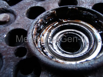
DMF Mercedes Sprinter Centre Bearing

Always inspect the centre bearing in the DMF, if this is damaged it is not available as separate part from Mercedes only as part of the complete DMF flywheel! The bearing itself is a special construction of a blind roller bearing made by INA that acts directly on the input shaft end of the gearbox, this is concentrically inserted into yet another single row ball bearing race pressed into the DMF.

Remove the clutch cover/pressure plate from the DMF, locking the flywheel with a small crow bar or broad screwdriver on the ring gear. You may have to pry the cover off its locating dowels, be aware it is heavy and it could catch you by surprise and fall on you!  Once this is out, you can inspect the flywheel face for damage. The outer DMF section of the flywheel should only rotate independently about 10-15mm in each direction at its circumference in relation to the other fixed half, any more than this indicates the likelihood of a worn DMF.  If you decide to replace this, you will need a long, large torx bit to undo the eight flywheel mounting bolts from the crankshaft. Once removed pry the flywheel from the crankshaft, it sits on a single dowel peg and can take some working to and fro to remove it.   Always inspect the centre bearing in the DMF, if this is damaged it is sadly not available as separate part from Mercedes, only as part of the complete DMF flywheel!  The bearing itself is a special construction of a blind roller bearing made by INA, that acts directly on the input shaft end of the gearbox, this is concentrically inserted into yet another single row ball bearing race which is directly pressed into the DMF.

Replacement of all the parts is exactly as the removal, although be sure to reference the ‘set’ position of the clutch before refitting.
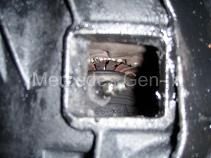
Sprinter gearbox inspection hole and bleed nipple >2006

Bleeding the clutch system can only be achieved with a Gunsons EzBleed or other pressure bleeding equipment, no amount of pedal pressing, as you would assume similar to brake systems will not work – trust me, you will be very lucky to achieve success otherwise.  Once you have a good pedal feel and the slave cylinder can be seen to be pressing the diaphragm springs back and forth fully through the inspection hole, start the engine. Now press the clutch pedal several times, you should often hear a light clunk, this is the clutch adjustment ring finding its own position.  Select a gear and test the clutch, all should be well.  If for some reason it appears as if the clutch is not fully disengaging and baulking you from selecting a gear, check your work regarding air in the hydraulic system, if re-bleeding it proves to be good, then try starting the engine in gear, handbrake on, with the clutch down, this will often by inertia, force the adjustment ring from its set position to its new working position, a second pedal press should now settle it into its new operating position and you should have a good responsive light clutch.
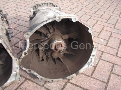
VW Crafter Gearbox showing concentric slave cylinder and thrust bearing

I hope you have found this information useful.
Mercedes SLK (R170) ABS Fault – Rear Reluctor Ring (Tone-wheel) Replacement


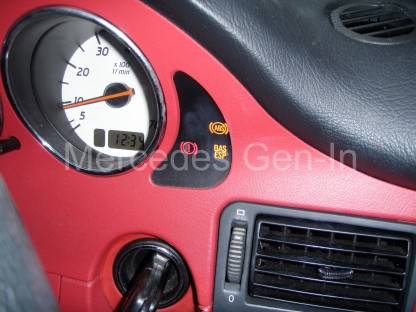
ABS faults can be complex to solve but often it is the simplest of things that causes those dreaded lamps on the dash.  If there is an issue with any wheel speed sensor arrangement on any corner, then this will prevent a number of things working correctly, namely ABS, TCS, ESP, BAS, Cruise Control/Speed Limiter and on the SLK power operation of the Vario roof too. So it needs to be fixed. It is now also a critical tested component in the UK MOT annual check – any dash warning lamps of this kind will immediately fail the inspection and prevent you from obtaining that valuable certificate.

Mercedes ABS Fault - Reluctor ring replacement 1

Intermittent ABS light faults are often attributed to dirty or poorly adjusted wheel speed sensors, even poor connections or weakly performing/damaged sensors can flag faults.  These faults are usually reasonably cheap to sort, though problems with the pump or controller can run into many hundreds to fix.  With this in mind, it is prudent to always check the simple things first, then move on to the ‘eye-wateringly’ costly parts when all other avenues have been followed and options exhausted.  So where to start…

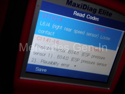
Fault finding can be very hit and miss without a compatible Fault Code Reader that can access the MB systems protocol. There are many on the market to choose from and probably the most capable will be from the Autel range. Be sure what you are buying covers the ABS system, as often less expensive readers only cover engine fault codes and leave the purchaser no better off when it comes to tracking faults in the ABS, SRS or other Body electronics. I use two or three tools, the most flexible and economical is the Autel 702 Maxi-Diag Elite, this can be purchased for under £150 if you search around for the best deal.

Mercedes ABS Fault - Reluctor ring replacement 2

However if you don’t initially want to run to that expense and you may be able to find a friendly independent mechanic who can read the system for you and tell you where the problem lies.  Do remember that if you go to a dealer for a code read, it is likely to cost around £45 to find where the problem lies.  You will then have to take it back to get the fault cleared once repaired, so as you can see you are getting pretty close to the cost of owning your own powerful diagnostic tool that will stand you in good stead for the future. If you have an older Mercedes vehicle pre 2000, then you will have less choice of code reader and things get a little more complex – you can catch up on older vehicle diagnostics here.

There are common faults that can cause problems throughout the Mercedes model ranges, no different with ABS than any other system. If you get unwanted ABS activation at slow speed, when rolling to a braked stop.  This is often caused by the wheel speed sensor on one or more wheels not detecting its rotational impulse cleanly.  This is called ‘falsing’. The controller is being fed an inaccurate stream of speed signal impulses that makes it think that one of the wheels is skidding and it applies (wrongly) the ABS to that wheel.  On W124 models, this was often caused by the magnetic speed pick up sensor devices on the front wheel hubs attracting metal rust debris, ending up looking rather like a christmas tree of iron filings.  The pulsed electrical induction signal from the sensor as its paired slotted ring on the rotating part of the axle whizzes by, is masked by the ‘growth’ of collected iron and rust on the sensor head, making what should be a very clean and precise tiny electrical signal, into a low level ‘blur’ in layman terms.  Simply removing the sensor and cleaning it up in a great deal of cases will result in a cure for this problem. If this does not cure the issue you will have to look more closely at the condition of the slotted or toothed ring that can be seen at the base of the sensor hole, this part passes the nose of the sensor as the wheel rotates.  On the front wheels of the vehicle this ‘reluctor ring’ or ‘tone wheel’ is often a vertically orientated slotted disk mounted behind the brake disk, attached to the rotating hub. Unless corrosion has taken its toll, the front tone rings seem well protected from the elements and do not often give trouble.

Mercedes ABS Fault - Reluctor ring replacement 3

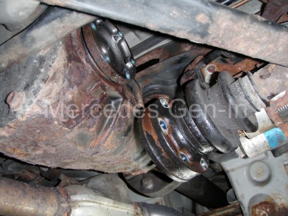
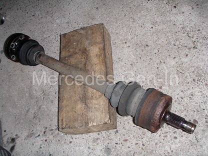
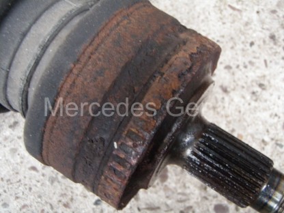
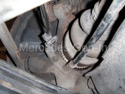
On the rear, most Mercedes cars have flat slotted punched-out reluctor rings ‘sweated’ onto the outer surface of the outboard CV joint casing, just as it passes through the hub carrier.  Often out of the factory this forms part of the complete half shaft and if it gets damaged a few years down the line, or as it often does – corrodes, then the complete drive shaft/joint had to be replaced at quite a tidy sum.

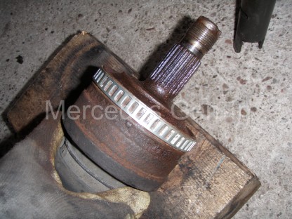
…Enter the wonderful world of the ‘Far East’ on that popular auction site. A wonderful factory somewhere in the world now produces just the 48 window (slots) 92mm reluctor ring (also common to SL R129 and many others) that you can fit to your existing half shaft and get things going for under £10 component cost. Needless to say it is quite involved to fit as you obviously have to remove the drive shaft from the vehicle to carry this out.  Link to reluctor ring seller.

Mercedes ABS Fault - Reluctor ring replacement 5

This article covers the fitting of a rear drive shaft reluctor ring to a 2001 Mercedes SLK200 R170, though the procedure will be common to many other MB models.  If you discover the faulty ring is on the side that has the exhaust passing by the drive shaft then you have a little more work ahead, as it often involves the partial removal of the exhaust system to obtain full access.  If however, if it is like in this case – on the right rear of the vehicle, no such removal is needed.

Reluctor ring replacement

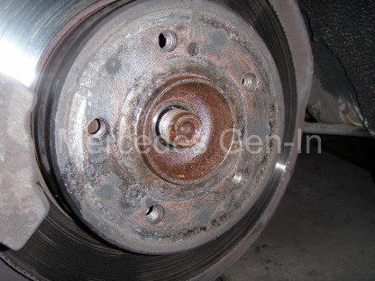
You may wish to initially remove the wheel sensor to protect it from accidental damage. Then you will need to obtain a 32mm 12 point socket. With the hub centre embellishment removed from the wheel (Alloys), with the handbrake set, in gear, while on the ground, peen out the locking tab on the hub nut.  Fit the socket and with the aid of a breaker bar, remove the centre hub nut from the end of the drive shaft.  Spray a good quantity of penetrating oil onto the shaft end so it travels down the splines within the hub. You may need to slip a tube over the breaker bar to ‘crack’ the hub nut off, as if not recently removed it will be very tight indeed.

Mercedes ABS Fault - Reluctor ring replacement 6

Now raise the vehicle so the differential is at least high enough to be able to swing a 21 inch breaker bar beneath the car (those inboard CV-to-output flange bolts will be incredibly tight) Chock and make sure your working area is safe then remove the 6 reverse torx bolts from the inboard flange of the drive shaft.  These have been thread-locked with a compound that must be the almost as strong as the bolt itself!  It will take some muscle to remove these pins, so be prepared.  Always seat the reverse torx socket on the pin with a copper hammer, not only does this ensure the socket is seated as far as it will go onto the head but the ‘rapping’ helps to jar and break the joint.  Remember – good well fitting tools are important here as if you twist up the head with an ill-fitting socket, you will be left with a huge ‘near impossible’ job to remove it.

Mercedes ABS Fault - Reluctor ring replacement 7

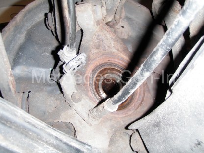
Once all six flange bolts and tri-plates are removed the shaft can be pulled down towards the front of the vehicle.  In some cases you will have to remove the plastic cover over the fuel pump to gain adequate opening to ease out the shaft end.  Its a tight fit, but it will come clear and hang down just below the nose of the diff.  Now take a copper drift and stout hammer and whack the end of the drive shaft, it should with a few blows begin to move, once it starts to move tap it with care so it passes through the splined hub centre.  Support the shaft as you tap and once free, guide it out from beneath the vehicle.  While it is off, check the CV rubber dust boots on both ends for damage/wear/cracks/splits as this is a perfect time to change them.

Mercedes ABS Fault - Reluctor ring replacement 8

Remove all traces of the old reluctor ring and file the surface clean to prepare it to accept the new ring. File deliberately more material off the outer edge to allow a slight taper lead-in for the new ring.  Once you are satisfied that the area is nice and clean and smooth, prepare to tap home the new ring onto the CV joint casing. Heat up the new reluctor ring with a blow torch, don’t go too mad, just enough to make it hot.  Then with a gloved hand, place it centrally and tap gently around the perimeter of the ring to drive it home into position.  In this case it was easy to see the exact location and position of the old ring, if you are not so lucky then use a torch to inspect the opposite side of the vehicle to get the correct placement dimensions you need.

Mercedes ABS Fault - Reluctor ring replacement 9

Once the new ring is fitted, the drive shaft can be assembled back into place and the other parts built up around it, much in the same way as they were removed.  Be sure to tighten the hub nut to the same position as it was prior to removal so the lock tab can be tapped back into place.  If you can obtain 6 new flange bolts for the reassembly, then that would be best, failing that be sure to wire brush the old screw lock compound from the threads before reusing.

Mercedes ABS Fault - Reluctor ring replacement 10

Once the vehicle is back on its wheels on level ground, insert the code reader into the OBDII diagnostics port, then read and clear the ABS speed sensor related faults from the controller. Finally road test. You will most probably now have no warning lights on the dashboard and be able to enjoy once more a fully functioning set of connected vehicle features that were all lost while the fault was present.

SPECIAL NOTES FOR LEFT HAND SIDE RELUCTOR RING REPLACEMENT

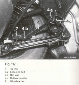
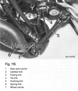
Because of the proximity of the exhaust and restrictions of access for the removal of the left hand drive shaft it is possible to remove the lower link bolt (lower wishbone to hub carrier), the ball joint of the tie link and hub end of the pushing link (lowest fixing on the hub carrier)  See diagrams below to identify component attachments to be removed. Once these fixings are removed it is then possible to pull the hub at the bottom just far enough out to allow the drive shaft outer CV joint to slide out its hub spline and hang down to clear the carrier so the new reluctor ring can be fitted.  Just remember to pre load the suspension as if the vehicle was standing on level ground before retightening the removed bolts.  This is a practical alternative method to removing the drive shaft completely from the vehicle.

Fig-117 Fig-116


Sprinter Fuel Rail Pressure Regulator Problems – Poor Starting


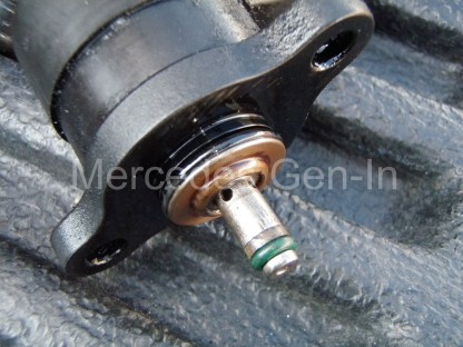
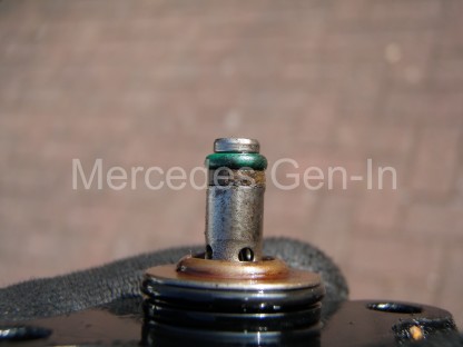
The Mercedes CDI series of diesel engines have an electronically controlled fuel pressure regulator mounted on the end of the fuel distribution rail. This controls, as the name suggests, the fuel rail pressure. It relies on the seal made between a single small O-ring which is backed by a split fibre backing ring.  What happens over time is that the O-ring wears and often fails allowing pressurised fuel to bypass the valve and ebb away the required running pressure that the injectors need.  Often the problem becomes more noticeable once the engine is warm and poor starting results.

Usual symptoms for this can be laboured starting when warm and occasional non starting, if the fuel rail cannot maintain the required minimum of approximately 300 bar at crank to allow the injectors to fire.  If it is possible to monitor rail pressure using Live-Data, you may see the rail pressure dancing between 266 and 550 bar. Instability of pressure when holding a steady throttle will be the clue as to a problem with the fuel pressure control.  If you do not have access to a compatible code reader thankfully the repair is simple and not costly so easy and cheap to eliminate as a cause of poor warm/hot starting. (Under £10)

Sprinter fuel pressure regulator fault 1

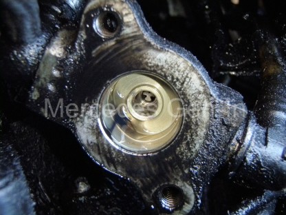
Remove the upper section of the inlet manifold to allow access to the rear of the fuel rail, just under and against the bulkhead/firewall.  Identify the electrical connector and remove it, select a 1/4 drive socket wrench and appropriate small reverse torx socket and short extension.  Remove the two opposing pins on the regulator flange (left and right as fitted).  Pull out the fuel pressure regulator from the end of the fuel rail.

Sprinter fuel pressure regulator fault 2

Keeping the device clean, remove both the green O-ring and fibre backing ring from the tip of the regulator and replace with new components.  Refit the regulator assembly to the rail.  It makes it easier if you have the left hand threaded pin in place in the regulator flange mounting hole, before offering it into place. (left hand in fitting position, if standing at front of engine)  Once the two pins are re-fitted the electrical connector can be attached and the intake manifold upper half rebuilt.

Sprinter fuel pressure regulator fault 3

Back of the fuel rail where the regulator mounts (normally hidden from view)

It is important to note that a failing fuel injector can also deprive the fuel rail of its operating pressure. If you suspect that this is the case, perhaps after changing the regulator O-ring to find there is no difference to the fault then you must carry out or entrust a garage to do a diagnostic ‘leak-off test’ to prove the injector system is sound.  WARNING a failing fuel injector that is passing unmetered  amounts of fuel can soon damage the engine catastrophically, either through piston overheat or engine seizure and any suspected problems must be investigated promptly!  See this interesting and descriptive forum post regarding leak-off testing.

Sprinter fuel pressure regulator fault 4

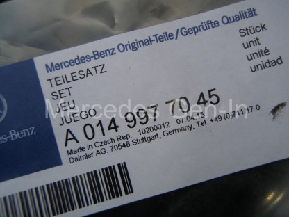
Fuel rail pressure regulator seal kit part number