Technical MB General

Technical non-specific MB

Mercedes Sprinter EDC Lamp – Putting right the ‘bodgers’ work

 
From time to time you come across things that just amaze you, and this customers Mercedes Sprinter van was no exception. The van had come in with an obvious ABS fault, sensor wire physically and visually broken, and no warning illumination on the dash. Once the ECU was read there were in fact several faults related to the engine that should have illuminated the EDC lamp too, but nothing!

Mercedes Sprinter Instrument Lamp Repair 1

After a bit of fuse-chasing and voltage checking, it seemed the problem was at the instrument pod end. It turned out the previous owner had removed the instrument pod, unclipped the PCB and prized it apart just enough to slide a small screwdriver in and break off the surface mount indicator LEDs. These should have illuminated showing the current faults. It was hard to say if this was actually a measure to disguise the faults so the vehicle could be sold, through maybe auction or otherwise or if it was a desperate attempt to get the vehicle through the annual MOT – Who knows…   All I knew was that before any other remedial work could be done this sensibly had to be rectified first.

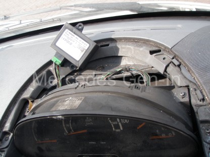
To gain access to the Sprinter instrument pod, first prize off the light grey facia moulding that contains the drivers air vent and switch banks. Tilt this around the steering wheel and let it hang to the floor with switch cables still attached. If you have more options and switches in place on both sides of the steering wheel it is best to label each and remove the electrical connectors from the switch backs, removing the panel completely. Do not be tempted to not mark what comes or goes to where, as several of the switch options have the same plug shape format with only different pin layouts. It is entirely possible you can plug the wrong loom plug into the wrong switch as they will fit!

Mercedes Sprinter Instrument Lamp Repair 2

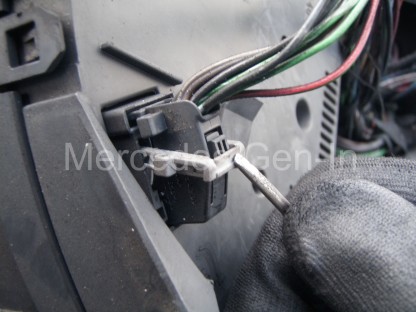
The removal of the facia reveals two screws either side of the instrument cover, these can be removed and the instrument cover lifted off and out of the way. A further two screws either side of the instrument cluster hold it in place and once removed the assembly can be pulled forward from the top, disengaging it completely. On the rear cover of the cluster you will see two multiway connectors, one grey/white one black. These have a special locking latch mechanism that releases them from the PCB. Just behind the lever on the plug body shell is a small press-in latch, once pushed, the locking release arm can be drawn over it and arced downward to horizontal. The action of moving this lever pulls and ejects the connector from its mating part, enabling it to be easily released and fully disconnected from the cluster. Unlatch both connectors and remove the instrument cluster to a clean work surface or bench.

Mercedes Sprinter Instrument Lamp Repair 3

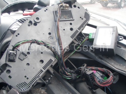
Around the removed instrument cowl is a series of clips, three at the top and bottom and one each side. Carefully unclip and release these, lightly pulling off the front cover of the instrument pod as you go. Once totally free the back cover can also be pulled from the instrument PCB.

Mercedes Sprinter Instrument Lamp Repair 4

To gain access to the LED indicator lamps you will need to pull off the dial servo motor indicator fingers. Grasp the centre black covers and unclip them, making note at this point of what came from where. Then grip the indicator pointers by their central hub and ‘pinch’ them off the spindles between forefinger and thumb. Be sure not to rotate the gauge stepper motor spindles as the correct position of the pointer will be lost. This will make repositioning the pointers difficult – without further powering up of the instrument cluster to reset the base zero positions, then agin aligning and refitting the indicator needles to accurately point to their associated rest positions.

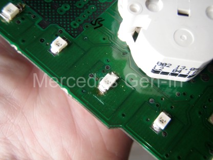
Once all pointers are removed, the black instrument face can be removed from the PCB. This is done by unclipping a series of protruding white clips at the back of the board. Once these are released the two parts can be separated, revealing the indicator LEDs at strategic points on the front face of the PCB.  Positioned so they illuminate and channel light to backlit icons screen printed on the instrument face.

Mercedes Sprinter Instrument Lamp Repair 5

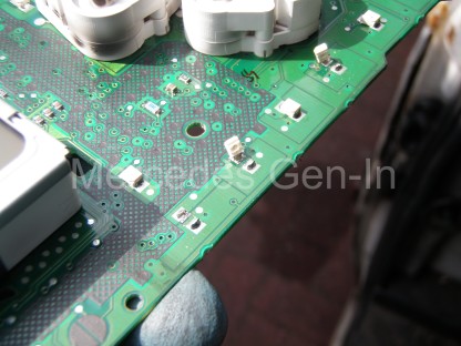
You can see from the photograph above what state the warning indicators were in and how they had been crudely levered/broken from the board. Fortunately only the LED components themselves had been damaged and not the copper tracks where they were attached. All I needed to do was remove the remnants of the old LEDs and attach new replacements.

Please note:I do have number of new yellow OSRAM SMD ultra-bright LEDs as used in Mercedes Benz consoles and if anyone has similar problems please contact me and I can arrange supply for a modest cost.

Mercedes Sprinter Instrument Lamp Repair 6

If you need to source Mercedes instrument panel LEDs – drop me an email to steve@mercedes.gen.in

Once the new LEDs were soldered in position (fitted to observe the correct diode polarity) the PCB was ready to be reassembled and fitted back into the van. Once reinstalled the ABS fault was rectified and the ECU fault codes cleared. This correctly extinguished the ABS lamps and left the EDC lamp illuminated – correctly warning us of our next engine related problem to be rectified!

Mercedes Sprinter Instrument Lamp Repair 7

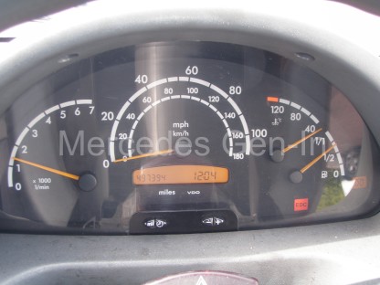
This issue truly highlights the importance of any potential Mercedes purchaser testing all the dash lamps in ‘ignition’ position to make sure all lights are illuminating correctly as they should in ‘lamp test mode’ before starting the vehicle. This point could easily be overlooked when buying a vehicle and turn out to be quite a costly oversight, so as you can see is this is a simple but very important check!

Sprinter Low Boost – Limp Home on Full Throttle

 
One of the 2004 long wheel base Mercedes Sprinters developed a problem where everything was fine under moderate throttle openings but once full power was called for, the van would register a fault and lock into limp home. Recycling the ignition cleared the fault, until the next wide open throttle and call for high power.

A great deal of work had been done on this particular van over a short period and most of the regular problematic contenders covered elsewhere on this subject had been dealt with. We knew we had good fuel delivery, good fuel pressure, sound boost and good induction hose-work. New sensors had been fitted on both low and high pressure points on the system and the only fault recorded was low boost.

Faulty Sprinter turbo boost actuator

We had previously seen another fleet operators Sprinter register low boost and discovered that the intake air filter was completely choked with muck and grime, this was not the case with this van.

Examining for mechanical issues became a primary focus as all the electrical systems were sound and cross-referring their readings on ‘live data’ proved their adequate function. In driving the vehicle with the code reader connected, we were able to see that maximum turbo boost was never achieved at full power, but was seen approaching moderate peaks at more modest and lazy throttle openings.

Often the van would perform fine unladen and fail consistently when loaded, slipping into limp home as soon as the driver tried to make good progress.

I removed the airbox and checked the vacuum pipework from the brake servo to the boost control valve and everything was in good order. I removed the supply pipe to the turbo actuator and double checked this for problems such as nicks, cuts and splits – nothing.

The lever arm to the turbo was free and this was confirmed by removing the circlip from the eye of the actuator arm and manually operating it to prove there was nothing wrong within.

Faulty turbo boost actuator Mercedes Sprinter

My next test was to push the actuator rod back into the actuator and be certain the movement was unhindered and smooth. The next test was to block the vacuum pipe opening with a finger, allowing air to be expelled while I pushed the rod inward. Closing the gap with moderate finger pressure should be enough to hold vacuum inside the diaphragm, making a ‘popping’ sound as the rod springs back to its extended position when you release your finger. I noticed the fitted actuator was not doing as it should in that respect as it was not ‘popping back’ to an extended position. Indeed, careful observation proved that the rod was moving very slowly to a fully extended position with a finger blocking the port, indicating a failure of the internal diaphragm – probably a slight leak or pin-hole.

This would under normal circumstances been difficult to spot as it had not failed completely. The actuator still pulled the turbo lever to a fully down position once the engine was started. However the small leak meant that the on-off pulse control of the actuator, given by the Pulse Width Modulation (PWM) of the vacuum control valve, was not as it should have been – resulting in under-boost on high power call situations.

The replacement of the actuator although fairly straight forward in mechanical terms, is a bit of a fiddle to accomplish, as one of the mounting bolts is a good finger-stretch into the confines of the turbo and takes some jiggling to get the pin back into position and tighten it.

There are three 10mm bolts into the exhaust side of the turbo scroll casting. These hold the actuator support bracket and also clamp the spool cartridge face against the turbo scroll casting flange making a gas tight seal.

Once these three bolts are removed and the circlip removed from the rod/lever, the actuator can be removed for inspection. Access to the area is best achieved by removing the complete air box, the turbo intake hose and brake servo vacuum pipe. Once these components have been removed, additional removing the vertical heat plate/shield that separates the air box from the turbo assembly is essential to obtain free access to the three actuator fixing bolts – especially as one is a real swine to get to!

Faulty turbo boost actuator Mercedes Sprinter 2

It is important to set the actuator arm/rod length of the replacement part to the same dimension as the original. This is critical in that it effects how the vanes are positioned within the turbo for any given actuator setting. Simply measure the new rod length to the old one and make adjustments using the 10mm lock-nut and thumbwheel provided on the actuator rod. Lock the setting once you have it and ensure the hole in the rod eye is positioned in the correct plane to accept the lever bar of the turbo once reinstalled.

Rebuild is the reverse of disassembly from this point. Once fully built, check your work and clear any remaining fault codes and then road test the vehicle. Once again boost should be available through the complete power range and it should react smoothly to engine loading, just as it did prior to the fault occurring.

Other Mercedes Sprinter turbo fault/boost related posts:

http://www.mercedes.gen.in/WP35/mercedes-sprinter-turbo-limp-home-los-diagnosis-fault-finding/
http://www.mercedes.gen.in/WP35/new-turbo-still-boost-mercedes-sprinter/
http://www.mercedes.gen.in/WP35/not-maintaining-sprinter-air-filter-can-leave-stranded/
http://www.mercedes.gen.in/WP35/diesel-mercedes-sprinter-turbo-rebuild/
http://www.mercedes.gen.in/WP35/mercedes-sprinter-turbo-blown-symptoms/
http://www.mercedes.gen.in/WP35/mercedes-sprinter-t1n-large-engine-oil-loss-leak/

Please be sure to use the comprehensive site search facility to find what you are looking for (Just enter your search term in the search box on the top right and click search) – There are many informative Mercedes posts on this this site, just waiting to be viewed!

Mercedes C Class (W203) Rear Damper Replacement

You may have already read of the problems here, including banging and knocking noises associated with faulty rear dampers (Gas strut/tube type) on the Mercedes C200 (W203). In this post we will detail how to easily change the faulty parts and get the vehicle back to specification.

Mercedes C200 Rear damper replacement 1

While neither of the dampers removed had any visible signs of fluid leakage and had recently passed annual inspection, they were exhibiting knocking noises on slow speed movement over uneven ground.  Internally a gas type damper has a charge of oil and a further charge of high pressure gas, usually nitrogen.  As they age the gas escapes through the damper rod seals and leaves just the oil to perform all of the damping.  When new, the purpose of the gas charge is to control small and light movements of the suspension, leaving the oil to take care of damping the larger travel and more violent bumps and bangs the car car is subjected to in normal road use. Calibrated internal valving controls the dampers rate and makes for a perfect combination of gas filled over hydraulic fluid dampers for vehicle use.  However once the nitrogen charge has escaped over age, the damper will have difficulty controlling the smaller reflex movements of the suspension.  larger travel may still be adequately catered for with just the remaining oil, but slow speed damping will, in most cases be poor.  Due to the resulting little to no light damping due to the depletion of the gas charge, the oil is having to do all the work. Working harder and forcing oil through the metering valves more rapidly to try and compensate, heats up the oil which often froths as it passes back and forth through the internal orifices.  Once air is introduced into the damper oil as frothing, it becomes ineffective as the air is compressible – any subsequent damping will be hampered by this condition.  Over time, as the shock absorber ages, the first leakage is often the gas charge. It is this natural ageing that requires some diagnosis and the faulty dampers replaced accordingly.

Replacement is very simple on the Mercedes C200 model series and both dampers can be easily replaced in about one and a half hours.

Mercedes C200 Rear damper replacement 2

First empty the boot load area, remove the carpet liners from both sides and base of the compartment.  There are two plastic mushroom clips at the top edge either side, once these are removed the carpet can be folded back to gain access to the strut tops once the hard plastic cross panel has been lifted.  To do this simply pull the two D shaped mushroom clips and disengage the panels forward edge from the plastic spare wheel well retainer lip. This black hard plastic cover can now be lifted clear of the car.

Mercedes C200 Rear damper replacement 3

Working one side at a time, undo the road wheel lug nuts and support the vehicle on a trolley jack. Remove the wheel and spray penetrant onto the two 10mm head, self tapping screws that hold the plastic wishbone cover in position.  Unscrew these two fixings and remove the plastic wishbone cover.  Now spray the 16mm lower suspension nut with a similar penetrating oil.

Mercedes C200 Rear damper replacement 5

If the dampers are original fitment they will have an inverted torx head damper bolt head and a 16mm nut on the other end, your replacement will probably have a standard 16mm nut and bolt included in the kit.  Place a support under the wishbone and lower the jack so the wishbone ‘just’ contacts the block and takes some of the tension from the suspension component.  Undo the lower damper nut and tap the bolt through.

Mercedes C200 Rear damper replacement 6

From inside the car use a 17mm spanner and undo the top fixing, you may need to hold the damper rod with grips to prevent it spinning as you fully remove the nut.  Now take off the top plate washer and then lever out the ‘rubber donut’ from the protruding thread and sleeve.  Discard these parts as you should have new components supplied in the kit with the new damper.

From under the wheel arch, use a stout screwdriver or short lever to force down the top of the damper so that it clears the mounting hole, once free, let it extend fully in a controlled manner. Tilt the top of the damper out into the wheel arch area and lift it free, pulling it out of the lower wishbone as you go.

Mercedes C200 Rear damper replacement 7

Refitting the new dampers is an exact reversal of removal, be sure to fully tighten the top securing nut and use the supplied lock nut to prevent it undoing.  Again you may need to use grips on the rod end to prevent it turning whilst you are tightening.

Once all fixing nuts and bolts have been tightened, refit the internal carpet and side panels.  Do not forget to refit the plastic protection panels to the lower wishbones, clipping them into position before fastening with the special 10mm head self tapping screws (2x per side)

Mercedes C200 Rear damper replacement 8

Conduct a road test and enjoy quiet safe motoring!

If you are interested have a look at the short 30 sec. video below, this shows how the first six inches or more of the old dampers stroke is virtually ineffective, though the lower section still has some damping capability. This is due to either gas escape or faulty/damaged/aged internal valving.  New shock absorbers/dampers transformed the vehicle over rough roads and totally eliminated the rear end knock at slow speed.

Mercedes C200 (& others) knocking noise at rear – Diagnosis

If you hear a thudding or knocking noise from the rear of your vehicle you will want to find out what is the cause pretty quickly as the constant noise will soon drive you mad!

Mercedes C200 Rear damper problem 1

On the Mercedes C200 and actually most Mercedes Benz passenger car models, that all share the long lived 5 link rear suspension set up, there can be several causes.  The first potential cause to eliminate is wear to the anti-roll bar bushes or sway-bar (US).  There is two bushes mounted to the chassis in D saddles that carry the roll bar from one side to the other, any any play here can cause thudding or knocking on uneven ground.  Usually rust staining gives away the poor condition of these busses – what happens is the bar corrodes inside them and presents a rough oxidised surface that eventually wears away the supporting rubber at it moves under normal use.  This is why it is good practice to file down, de-rust and repaint any exposed metal before fitting new bushes.

Mercedes C200 Rear damper problem 2

On each end of the roll bar there are drop links (like a dog bone in shape) these have a rubber bush at both ends and connect the roll bar to the suspension hub carrier. It is important to check the condition of these rubbers also. In both of the above cases it is important to inspect all bushes while the vehicle is on all four wheels and in its normal driving position, as lifting one wheel will put the connected bar in tension and you will be unable to see the small amounts of play that would be more than capable of causing knocking noises.

Mercedes C200 Rear damper problem 3

If all looks sound and no play is present, turn your attention to the rubber bushings at each end of all the suspension links, use a pry or lever to check them for play. These bushes do deteriorate and although sometimes looking in poor condition, cracked on the ends with rusty sleeves, they are still serviceable as long as they do not allow lateral movement where the arm could contact its mounting.  Play of this kind would be severe and easily noticeable under power or braking.

The noise you will have most difficulty in finding the source of will be the one that comes and goes at slow speed on uneven terrain, it will be irregular and probably most prevalent while crossing speed bumps or rail lines on a crossing.  If you have checked out all the suspension components, exhaust mountings and interior of the boot area you will be turning your attention to a faulty damper.  As these deteriorate over time they will in most cases eventually cause a knocking as the valving begins to break up internally or in severe cases the internal oil is lost through leaking. The simplest way to check for a faulty damper is shown in the following short video.  Quite often it is possible for a car to pass an MOT test with a faulty or ageing shock absorber, especially if it is secure in its mounting and not in any way leaking.  It is only as the units age that they gets weaker in operation and eventually often fail,  providing little in the way of suspension damping at all.

Mercedes Diesel Injector Seal Replacement – Notes

In a recent Mercedes Sprinter engine replacement (Used engine fitment) it was noticed at the time of purchase that there was an issue with No.2 Injector seal leaking. Obviously this needed attention and there was more chance of being able to remove the stuck injector once the engine was fitted, than try to do the work on the engine prior, as it would simply move around the floor with the physical effort involved!

What I did do before fitting the engine was to get rid of all the carbon ‘Black-Death’ build-up due to the leaking injector. This involved careful chipping and clearing the cables, connectors and pipes that were buried beneath the charcoal coating. If you want a really clean and sparking job, I can recommend a none-acidic oven cleaner for a final dressing, but in this case it was cleaned to a ‘practical degree’ that fitted with the age and condition of the vehicle.

Mercedes Diesel Injector Removal and Fitting 1

Without a doubt, if you are able to start the engine and get it warm, even loosen the clamp bolts five or so millimetres above the shoe clamp then rev the engine, what often happens is the injector gets ‘blown out’ a little under engine compression and once the carbon seal is initially broken, it can make subsequent extraction a great deal easier.  Sometimes it works – sometimes not!

In my case I knew that the engine would probably not start as the seals were in such bad condition. As I turned the engine over clockwise using a 27mm socket/breaker-bar on the crank nut, you could hear the escape of air past the injector seal on each rotation. This was confirmed by localised spraying of WD-40 onto the suspect injector and watching it bubble/vaporise as air from the combustion chamber was forced by the injector during a manual rotation of the engine. I had to proceed without heat or hot engine – always makes for interesting removal!

Mercedes Diesel Injector Removal and Fitting 2

Obviously you will have to remove the inlet manifold upper half and also the engine cover if fitted before you can gain access to the injectors. It is important to plug all the intake tracts to prevent items such as the bleed off pipe spring clips finding their way down there etc…

Once the engine was fully installed, the injector power plug was removed, the bleed off return pipe unclipped and moved well out of the way. The steel diesel supply pipe and the injector union connection were removed with a 14mm spanner and 13mm socket respectively. As soon as the union was removed the hole was plugged with a small section of kitchen towel pushed into the tapped hole. This simply prevents any bits getting into the open hole while working to extract the injector.

Rarely it is possible to clamp a pair of good mole grips to the injector solenoid fixing nut and rotate the injector ten or twenty degrees back and forth to loosen it in its bore, more often it takes a great deal more work!  Using a searching penetrant or diesel itself is a good aid to getting things moving. This twisting method can be successful, though what usually happens once you start to get going is that the fixing nut undoes slightly and puts a stop to using that method of extraction, as it simply rotates upon the head of the injector body.

What you have to do in this eventuality is grip the injector just below the solenoid nut and attempt to move the cast head part – rotationally back and forth. As the diesel supply union is completely removed, you will get the maximum chance of realising this important few degrees of movement, that will in time result in the total removal of the injector body.

If you have a 24mm open end spanner or its imperial equivalent this is your key tool. If your area of work is the rear three injectors there is a little technique that may work for you. If you lay a 19mm combination spanner along the top of the duct that carries the injector wiring, interlocking the open end into the rear intake manifold support bracket, this will provide a sturdy supporting surface on which to lay the ‘operating’ slightly slack fitting, 24mm spanner onto whilst moving it back and forth. As you will probably only be able to shift the injector a few degrees back and forth at first, it is important to keep the area well irrigated with penetrant. As your movements get more dynamic, begin to press the back of the operating spanner down onto the 19mm rider. Keep pushing as you rotate back and forth. This induces a small lifting force under the solenoid nut from the 24mm spanner and as you move it, it will in time begin to raise the injector out from its bore. If your injector is at the forward end of the engine you will have to locate the 19mm ‘rider’ spanner’s open end somewhere up-front to fully enable this method, but it is not impossible!

Sprinter Diesel Injector

Mercedes CDI Diesel Injector

Eventually you will extract the injector – a feeling of achievement will appear as you take an inspection mirror and torch to peer into the blackness from where it came. If you were lucky then the copper washer/seal will have accompanied the injector out of the hole.  If not, a ‘rat-tail’ round file of suitable size, pushed into the hole will retrieve the seal without issue.

Now you can begin to inspect the seal itself, giving up many clues to the demise of its capability to hold pressure. Clean it with a rag and take a close look at its copper surfaces. If there are any scored lines, cuts or deep marking, this is the route the escaping combustion gasses have taken to ‘carbon-up’ your engine with ‘Black-Death’. Indeed any gas-cut passages in the sealing surfaces will have most certainly also cut into the aluminium injector seat and in severe cases damaged the steel injector face that mates with the copper seal.

I would recommend always at least cleaning the recessed seat of any removed injector with a special tool made for the job. This special tool is a flat face end-mill or reamer with the correct diameter sleeve to cut or reface the base surface with some precision. These tools are available from Laser for under £60 from most motor factors and are essential to DIY replacement and the successful re-sealing of injectors – experience has found in every case, if you don’t at the very least ‘lightly face’ and prepare the injector seat before reinstallation, you are not giving yourself the best chance of success, therefore I would get the proper tool for the job, period!

Mercedes Diesel Injector Removal and Fitting 3

Escaping combustion gasses often cut the aluminium seat and this needs to be re-faced so that a perfectly gas tight seal can be maintained

One or two rotations with the seating tool will be sufficient to enable you see if the seat is damaged in any way, using your inspection mirror and light. If there are any black marks on the seat (rather like worms!) as the drawings below show, then continue to use the seating tool, checking and wiping aluminium shavings as you progress to remove material. Eventually the tool will re-face the damaged seat to show a clean, uninterrupted ring of aluminium. It is possible if you do not fully rotate the tool when using it, mistakenly rotating the tool left to right rotationally, may cause the finished surface to have ‘chatter’ marks on it. This is surface unevenness that must be removed and is only achieved by turning the tool lightly and continually in one direction, stopping movement only as you simultainiously relieve pressure from the cutter. Inspect and clean often, to obtain the best surface finish possible.

Mercedes Diesel Injector Removal and Fitting 5

Improper use of the seating tool sometimes causes chattering on the surface of the seat. This needs to be smooth and not disrupted with tool marking

Now turn your attention to the face of the injector body that compresses against the copper seal. This must be free of any carbon build-up and ‘shiny clean’. You can take some fine emery paper and lightly work this surface until it is bright and continuously clean around its circumference. Now you are almost ready to reassemble!

The injector hold down bolts are a one-time-use, stretch to yield fastening, that must be new and unused on each replacement. Cut a short groove with a saw file to make a thread cleaner out of the old bolt and use this to freshen up the tapped hole for the clamp bolt. Use a thin screwdriver to clear the oily debris from the bottom of the hole as it often builds up here and can if not removed, be forcefully compressed into a plug, causing it to burst through into the cylinder head water jacket – take special care to clean this hole out!  If the thread is damaged in this deep tapped hole you have a number of repair options, these are covered briefly in this post.

Mercedes Diesel Injector Removal and Fitting 6

Now you can use ceramic grease to coat the outside of the injector body (not the tip or any mating/sealing surfaces) place a new preferred Honda Accord Diesel Seal onto the injector tip and carefully lower it into the clean and prepared hole. Do be sure to have one final check with torch and mirror to make doubly sure there is no debris left on the sealing surface before final assembly. Once the injector is fully inserted, with the fuel connection pointing to the fuel rail, add the clamp and loose-fit the clamp bolt to hold things in place. Now refit the fuel union to the injector, removing the tissue plug that has prevented dirt getting inside, then refit the steel fuel line from the injector union to the fuel rail, finger tightening the union nuts. Now torque the clamp hold down bolt to 7Nm plus 90 degrees (MB Specs say 90 plus 90 degrees after 7Nm, but actually the yield has occurred after the first 90 degrees and clamping force reached, so I see little point in risking further stressing an otherwise ‘spindly’ and fragile fixing). You may now refit the fuel bleed off pipework, electrical connector and tighten off the steel fuel line unions. Rebuilding your engine is now a reversal of dismantling. (remember to remove the manifold intake plug of rags or paper before fitting the upper section!)

There are a few tips here that hopefully will help you achieve this sometimes daunting job, but with care, patience, the right tools and a little effort this can easily be done by a DIY mechanic.