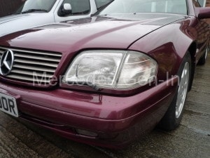
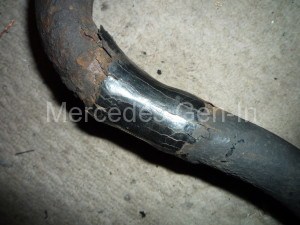
The SL’s radio antenna was just a 4 inch stub neither moving up or down, completely jammed, a service and repair was needed.
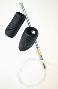
Being the standard OEM antenna fitted to this car I knew it would be worth the effort as the Hirschmann ATUA 6000KE is an expensive and fine quality unit with every spare part available from Hirschmann. The antenna mast type for the R129 SL is the h04 which is the 86cm chrome mast or the h05 86cm black chrome mast finish. Either mast will fit the 6000KE.
The Hirshmann h04/05 masts are equivalent to the Mercedes Benz part numbers B 6 6 82 8037 and Q 52223112
To remove the antenna pull upward the outer of the 2 part wing grommet and remove it, take a 13mm spanner and place it on the mast nut and unscrew it from the main body. Have an assistant turn on the radio and the antenna should feed out of the main body until the plastic/nylon mast gear disengages fully from the internal drive allowing you to withdraw the mast completely. Oh if were that simple…
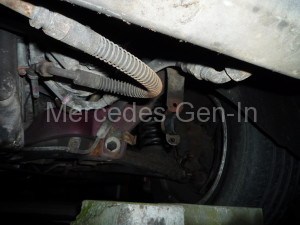
As I previously stated the mast was jammed (as the top photo) and did not move at all, so the complete antenna has to be removed from the car.
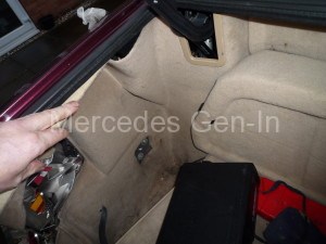
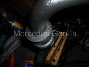
Unclip the inner lamp housing and disconnect the electrical plug, place to one side. From the photograph you can see that I had to remove the OEM Blaupunkt CD changer from its bracket before remove the interior trim to the left hand inner wing from inside the boot. Look towards the base of the antenna motor and inner wing support bracket and you will find a single cross head screw – undo this. Remove the ground braid from the support using a 7mm spanner/socket. Remove the plug from the motor controller and unscrew the antenna cable from the upper section. You can now manoeuvre the motor assembly and rod down and out of the rubber wing grommet and out of the vehicle.
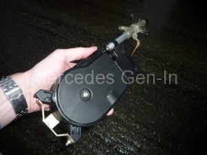
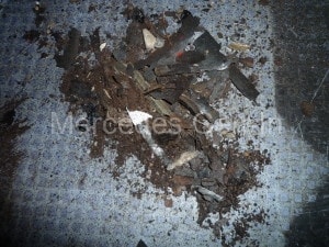
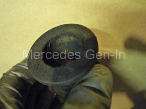
Once on the bench things are more accessible and obvious. If you could not remove the antenna mast from the tube then carefully clamp the upper tube section in a vice and remove the mast. It may be corroded in the top section of the tube if its been there for a while so a little jiggling and pulling may be necessary to fully remove it. As the mast will not be reused twist it round until the nylon rack attached to the mast breaks and discard the antenna. Now remove the top tube casting (antenna connection section) by unscrewing it from the ally tube.
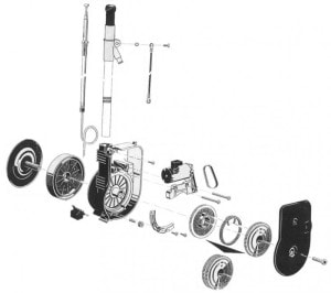
You will now be left with a black motor body and alloy tube section. To retrieve the broken nylon rack and service the internal parts undo the single torx screw on the centre circular hub and remove both the rack cover and motor gear covers on either side. Pull off the black rack spool and uncoil the contained nylon rack. Turn the assembly over and begin to tease the nylon gear out from the worm drive, this is a little tricky but will pass the worm drive with a small clearance. With this split gear removed remove all the old debris of nylon rack and clean the body. Use a stiff nail brush or old tooth brush to clean the drive components, WD40 helps to loosen the muck.
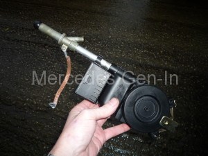
The motor control electronic section slides off the main body away from the alloy antenna tube, there is a twin electrical connection to the motor. If you further remove the 2x torx screws from the die cast zinc motor chassis it can be withdrawn from the plastic main housing. The small black drive belt that runs from the motor sprocket to the worm drive can now be replaced. While you have this apart lubricate the bronze bushes on the worm drive spindle and refit.
Working from the motor side of the casing remove the white plastic quadrant/guide at the 7 o’clock position (2x cross head screws) Be sure to clean this before refitting. Beneath this quadrant is a small steel roller and bearing pin this needs to be cleaned and lightly lubricated, once done this part can be built back up.
Replace the empty spool assembly on the rear of the main housing, refit the split two section nylon main drive gear and refit the cover. the motor controller can be slid into its home position at any time.
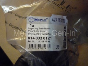
If you discovered any parts broken, especially the two section drive gears their internal spring, the drive belt etc they can be purchased from a Hirschmann dealer or even from EBay!
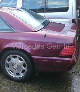
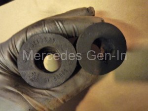
The repair parts, h04 h05 replacement antenna masts with integral toothed flexible drive rack, and mounting grommets can all be purchased at the very best prices from EBay seller ‘car-masts-uk‘ or simply email him for a price. (Although these are not a cheap product by their nature, I doubt you will not find them cheaper anywhere – as I looked!) The importance of the grommet condition is to prevent water entering the trunk/boot and corroding the wheel well area behind the rear wheel and is best replaced if found to be suspect. While the interior trim was out I took time to inspect the roof operating hydraulic cylinders for problems and thankfully no leaks and in fine condition.
Refitting is the same as removal. once you have installed and reconnected the motor assembly (the antenna motor should now run) feed the new antenna mast rack down into the open tube. (It is designed to feed into the gears correctly so don’t worry too much about the initial orientation of the mast/rack when inserting it for the first time. If it does not grip first time rotate the mast slightly then it will drive home easily) Once the mast rack is grabbed by the drive cog it will begin to retract – feed the mast home carefully until the chrome part just depends into the tube then begin to screw in the mast nut finger tight. The motor will stop at some point (usually with several inches of mast protruding) allowing you then to fully tighten this nut. Turn on the radio for a moment until the antenna fully extends, then turn it off so that it fully retracts. You may have to do this a couple of times to set the antenna so it extends and retracts correctly. Replace the outer grommet and check everything works and the antenna lead is connected before you replace the interior trim. Once completed I will valet the boot-space to make it all the more pleasing!

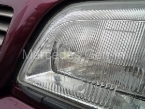
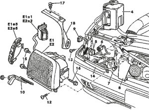 Once you have the lamp removed, the lens glass can be removed by firstly removing the L shaped rubber bonnet/hood seal from the outer case by pulling the centres of the plastic rivets that hold it to the lamp body. Once removed you will see 4 clips reaching from the glass lens housing to the main body, 2 on top and 2 underneath the headlamp assembly. Using a paint scraper or similar tool lever each clip up just enough to push the housing apart. Work your way round to release all four clips then withdraw the lens away from the main body. You will now see the lamp seal in its groove. This can be removed and cleaned before reassembly. You may now carry out any repairs you require inside the lamp before reassembling and refitting the lamp housing.