Tools

Tools

Mercedes Sprinter / VW Crafter simple bodywork repair

If you own a commercial or working vehicle, from time to time you will without doubt attract the odd knock or bump along the way that adds character to your van.  Not everyone wants to pay premium bodyshop prices to rectify these scars and in many instances its just a matter of keeping the van respectable and not looking like an old hack.

For this reason I have added this post, hopefully to give you some confidence to carry out your own simple bodywork repairs, especially if it is something you have never tackled before. Before we begin I will point out that any DIY repair will often fall short of professional refinishing to that showroom standard, but if you are looking to tidy up a few knocks and bangs to a reasonable ‘working vehicle’ standard then read on…

Any length of time you invest in putting right bodywork wrongs, is directly proportional to the quality of the end result. It is worth remembering that a ‘quick-job’ will more than likely look like one, so be prepared to spend some time to do things properly and get the best results you can.

Mercedes Sprinter DIY Bodywork Repair

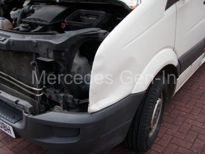
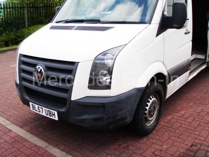
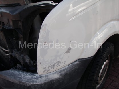
One of my clients drivers made a clumsy turn-round manoeuvre in one of the LWB Crafter CR35’s and being one of the tidiest and latest vehicles on the fleet it seemed a shame to leave it in a state of disrepair.  The price of a good white painted second hand wing was in the order of £250 and a 100 mile round trip to collect – not what he was looking to pay.   Any professional body repair work would mean time off the road for the vehicle and currently this would not be possible, so I offered to to rectify the damage over the weekend.

Mercedes Sprinter DIY Bodywork Repair 1

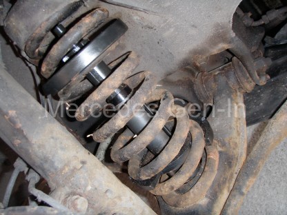
Here you can see a photo of the initial damage, fortunately the lamp assembly was not in any way broken so the repair was confined to the wing panel itself.

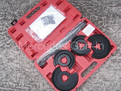
Half the battle of any body repair is having some kit to help you, this will not cost you the earth and it will always be on hand for any future jobs that you may wish to take on.  The remaining half of the battle is having the ‘balls’ to take on the job of physically hitting out the dent – especially if its something new to you.  What you have to remember before you start is – you can’t make it any worse really can you!

Mercedes Sprinter DIY Bodywork Repair 2

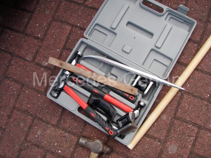
I use a cheap and cheerful Panel beating set from Machine Mart, costing around £35 for a comprehensive set of hammers and steel dollies. As I am no panel beating or bodywork expert, this is about the maximum I am prepared to invest to get the job done.

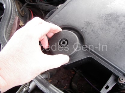
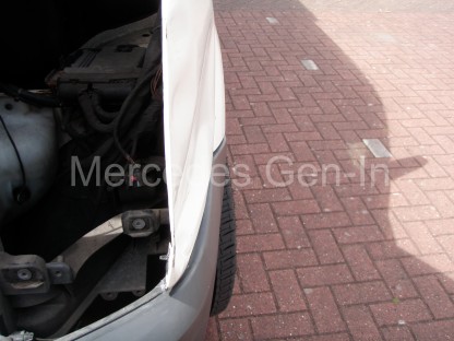
First I removed the grille, headlamp assembly trim panel and lamp unit.  This revealed good access to the back of pretty much all the area of damage.  This is ideal.  If the dent you wish to get at is further back, then you would probably have to strip out the plastic wheel liner and remove the road wheel to gain suitable access.

Holding a steel dolly on the outside of the wing, strike the inside of the wing/dent to start to bring it outward.  Don’t worry about over-bending it slightly at this point as you can aways dress it back.  Moving the dolly about to absorb the hammer shocks, try and model the wing to its original contours and shape.  Once the outline shape starts to recover, reduce the force of your hammering and begin to strike the point where the dolly touches the point on the surface of the outer wing.

Your hammering sound will change when you start to hit the correct point, it will begin to ‘ping’. This means you are striking the metal perfectly, sandwiched between hammer and dolly, flattening the rippled and dented steel as you proceed. If your dent is horizontal, work vertically in lines, up and down over it to work out the kink in the metal sheet, if your dent is vertical, do the inverse.

You will soon get the hang of tapping with the flat faced hammer and deforming the metal, flattening it onto the dollies.

Mercedes Sprinter DIY Bodywork Repair 3

Take your time, use the range of dollies in the kit to access all the areas needed, use the wedge dolly on the panel lips and edges and the flatter anvil types on the more linear surfaces.  The original shape will begin to emerge.  Any high spots on the outside, reverse the hammer and dolly to knock the panel in onto the anvil, working from both sides of the steel where necessary.  There is a great little web article on Panel Beating for Beginners here should you wish to read up a little more before you attempt your repair.

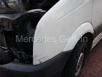
It should be possible with careful work, to get the shape of the original wing back without the need to use large amounts of filler or bonder. To be truthful, only a light skim of filler to flatten any imperfections should be what you are looking to achieve in your panel beating.

Mercedes Sprinter DIY Bodywork Repair 4

Test the fit of any components that may have a closing or butting edge to your work, be sure that everything aligns as it should.

Now rough-up and sand the repair surface with abrasive paper and a block, you will begin to see any high/low spots, re hammer if needed.  Apply a thin coating of filler where needed and sand flat when hardened, any imperfections address with more filler and sanding.  Work your way down in abrasive paper coarseness to obtain a smooth paint ready surface.

Suitably mask off any area that is likely to be subject to overspray. Be sure to use a primer of similar colour base to the top coat e.g white primer for white, grey for blacks and blues, red for red and so on.  It makes a difference to coverage and the final shade of top coat, so choose with some care.  Be sure to sand down each coat of primer to a smooth finish.  The primer itself will begin to fill small imperfections in readiness for the top coat, each coat of primer improving the chances of success with the top coat factory colour.

Mercedes Sprinter DIY Bodywork Repair 5

Wipe down the area and try to make it as dust free as possible before spraying with the factory colour.  Only apply light coats and let it dry between sprays, building a good thickness of paint is important that can eventually be cut back and polished.  Use a good coating of paint, I used almost a full can of top coat on this small area, this allows for any flatting or buffing without wearing down to the primer coat.

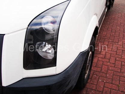
After leaving to dry for a good couple of hours you may begin to carefully build up the rest of the van, grille, headlamp and so on. Do not attempt to work on the paint for a least a day has passed, as it remains soft, even if dry to the touch, for several days before it is fully hard.

I think you will agree that the repair was a success and in actual cash value (not counting any time) it cost £60 to complete, this includes the tool set and materials.

Mercedes Sprinter DIY Bodywork Repair 5

Mercedes older series diagnostic fault code reading. W124 R129 & others

Mercedes older series diagnostic fault code reading. W124.R129 1980’s – 1990’s era

As you are reading this you will probably be wishing to extract a fault code or clear a fault indicator lamp from the dashboard of your older Mercedes Benz model vehicle. You will have also likely been frustrated by reading a multitude of confusing information, following dead web-links and generally reading several different takes on the same subject – mostly from well-meaning members on forums or online motor clubs who unintentionally ‘muddy’ obtaining the most correct and technically accurate information.

Well the alternative information source you have been looking for is here, hopefully clear and accurate enough for your needs. I have collected the following information together in one place to save the frustration of trying to locate and find most that you would ever need to tackle this job.  I will not repeat what has already been expertly written on this subject, you can find links below to these sources to expand on what I have noted here.  What I have done is written about the important parts and included some vital pieces of information that you may need to refer to – you may find this data at the other linked sources too, but at least it will remain available in another Mercedes resource should any of it disappear from the web, as a great deal on this subject already has.  Enjoy!

Carsoft Interface connected to R129

Carsoft Interface connected to R129

MB Diagnostic History

Back in the day when Mercedes first ventured into the world of on board diagnostics in the era of the 1984’s W124 and its stable mates they began to introduce electronic code diagnostics. The first being either through an 8 pin (X92) or 16 pin (X11/4) square block fastened to the bulkhead. There were actually only14 diagnostic pins on some 16 pin X11/4 models as slot 2 was a small momentary push button and slot 4 was a small red LED used to read out fault codes flashes. All was needed was a paperclip or short banana plug jumper to ground the required pins and simply watch the number of flashes. Codes are resolved from comparison of flashes to fault codes on a written list.

Counting flashes activated by grounding individual pins continued through the square block connectors to the 38 pin round X11/14 diagnostic socket to about 1994. This was commonly located within the ECU box and was accesses by removing a sealed access cap. Although 38 pins were used only the pins relating to build options were loaded and as such gave diagnostic flash / blink access to the cars individual modules.

Mercedes SL Diagnostic Socket

USA and some EU versions around 1994 were equipped with both a 38 pin X11/14 and the now common 16 pin oblong OBD port we use today. The reason behind this was that MB at the time had to comply with export requirements that necessitated access to emission data through OBD standard protocols. At this time Mercedes added the OBD port under the dash, in some cases near the steering column just to give access to emission related diagnostic codes, all the other electronic systems were dealt with through the 38 pin socket as before. So very much a hybrid situation was in existence – seemingly done as a quick fix to continue to sell cars in the US.

Mercedes were in parallel developing their own digital diagnostic system and not following the industry standard of OBD1/2. From August 1995 production date Mercedes phased out the analogue type of flash/blink diagnostics in favour of their propriety digital code reading system. Without going into too much detail this new system used ISO9141 communication protocol to access the vehicle electronics via a common communications module. This used both a K-line and L-line connection and Mercedes own communications language to access the system. Even though the communications standard of ISO9141 is the same as used on OBD2 systems the way in which it talked to the modules was bespoke – and this is why you cannot use traditional OBD2 readers on systems of this type. Fortunately Mercedes saw the error of their ways and only ran with this for about a six year window opting to take on the OBD2 standard across the board from 1999 (Thank goodness!)

Types

So given the above history there are three primary diagnostic code reading methods (actually four) that you may come across in the model year window of 1984-1999 (Please note all dates stated are approximate and for guidance only) What is a little confusing is that Mercedes in their wisdom used the 38 pin diagnostic connector for both the analogue and digital systems making it very difficult to visually identify what system you are dealing with – they even used the same pin number allocations to reflect the connection to individual system components !

The diagnostic systems that were available during this period are:

…………………………………………………………………………………………………………………..

Flash / Blink – circa 1984 – 1994
Flash / Blink with OBD X11/22 Under-dash for US Markets circa 1993 – 1997
                        (OBD Port for engine management only)
Mercedes Proprietary Digital Diagnostics 1995 – 1998
OBD2 Standard 1999 – on

…………………………………………………………………………………………………………………..

Useful links that have great information and should be used for reference. 

http://www.mbcluster.com/Media_Diagnostics.htm
http://www.202tech.com/howto/leddiag.html
http://www.onboarddiagnostics.com/page03.htm
http://k6jrf.com/mb_scnrs.html


Here is some important information that budding MB SL R129 / W124 diagnosticians will need.

To build and use a simple Mercedes Flash / Blink decoder,  here is the circuit diagram.

Simple Mercedes Flash Code reader

Here is the link to the Cs1000 Baum Tools Manual code reader that contains most of the detailed information you may ever need regarding, connections, pin outs etc specifically for Mercedes Benz models. Importantly it contains the analogue flash / blink error code fault decoder information.

To read codes:

1.Connect the code reader cables to pin 1 for the black or ground connection and pin 3 for the 12v supply on the 38   pin diagnostic socket.  Select your chosen test point (module connection) to test from the following 38 pin socket diagram and connection pin-out table.
2.Turn ignition on, engine not running.
3.Press momentary switch for 2-4 seconds, wait and then count flashes.  Note down the number of flashes on a piece of paper. Repeat the process until the first flashed code repeats.
Note:A single flash means  – no fault stored

To clear codes:

1.After reading a code, press the momentary switch for 6-8 seconds then release.
2.repeat this for all stored codes.


Mercedes SL R129 38pin Diagnostic connector pin out diagram and function list.

Please note not all pins are loaded in every model, the quantity of available pins depends on model, version and fitted equipment.

38pindiag

Untitled.xlsx


Later MB Proprietary Digital Diagnostic Communications – 1996 MY (R129)  SL

I have discovered that this period model (The one I have!) was fitted with a combination of both analogue (Blink / Flash) and Digital Mercedes Proprietary diagnostic systems.  I do not have an OVP module (voltage controller) I have a Base Module.  The base module can be accessed with the blink/flash code reader, faults read and cleared on pin 8, while other system components can be accessed with the Mercedes Proprietary reader from the same socket!

However that is about the extent of any function accessible by this method.  As stated earlier above to read engine codes or ABS codes etc the unit has to be connected to a capable electronic code reader.  The Autel OBD2 reader I use for most of my modern day Mercedes diagnostics does not work – even with the OBD 16 pin to 38 pin adapter.  This is because the protocol or access language is specific to Mercedes.

About the only system capable of reading and accessing the majority of codes through the Mercedes proprietary system is the Carsoft V12 system.  This is a Mercedes single model diagnostic tool made in Belgium.  Its kit consists of a 7.2 interface module, selection of leads (for all MB models) Operating USB security dongle and Carsoft V12 PC software.

I will cover the use of this diagnostic equipment in another post shortly.

For those fortunate to own post 1999 vehicles of the R129 stable your car should be equipped with a fully compliant OBD2 diagnostic system, 16 pin standard diagnostic port and the capability to be interrogated by most any off the shelf OBD2 reader. (Lucky you!)

Air conditioning system – self diagnosis (R129)

The AC control unit in the R129 Mercedes SL model along with a few other MB models of the time (outlined in the CS1000 manual) could be accessed to diagnose system problems by retrieving fault codes directly from the AC control unit console in the car.  Instead of counting flashes, the AC console displayed fault codes on the two digit LCD temperature display and were cleared by a combination of pushing buttons.  Information for the reading and clearing of the diagnostic codes of the AC unit for the R129 can be found on page 90 of the Cs1000 Baum Tools Manual.  Information on other period MB models that had similar AC control consoles is included in the above publication.

Mercedes SL (R129) Front Coil Spring Replacement

A slight difference in ride height on the drivers side front was noticed from when I purchased the SL over Christmas, so it was no real surprise the spring refresh needed doing.

Mercedes SL R129 Front spring swap 0

I put the spring job off (waiting for slightly warmer weather) and it jumped the queue slightly when a torsion bar hanger snapped, obviously because of the constant tension the weak spring was placing on the hanger arrangement.

Mercedes SL R129 Front spring swap 1

I ordered up a new pair of the front torsion bar hanger brackets and clamps from the local Mercedes dealer at £13.00 each. (Part numbers: A129 323 0026, A129 323 0126 and two clamps A124 323 1140) and a pair of 15mm diameter OEM replacement road springs.

The job itself is pretty straightforward and requires a Mercedes specific ‘special tool’ to compress the coil spring on the car to enable you to lift out the old spring and simply slot in the new one. With the specially designed tool, the job is very quick, though if you want to separate the ball joints and remove the torsion/roll bar then I have read some reports of being able to do a spring change without the spring compressor, undoubtably by levering the lower wishbone down – Personally for the cost of the tool, (£50) its not worth making the job ‘ten times bigger’ with the increased risk of doing an injury to yourself or someone else – Get the tool!

Mercedes SL R129 Front spring swap 2

Jack the car at the front from the jacking point and remove the road wheel. Slide into the spring the top plate of the compressor tool, locate the bottom plate and thread through the hole in the wishbone the telescopic compressor bar. Locate the upper bar tangs through the top plate by turning the bar until the top plate locks into its slots. Pay attention to align the bottom plate correctly as you begin to ratchet up the compressor bar. (19mm socket) Make sure all is located correctly with the compressor and the tool top plates, recheck as soon as you begin to feel tension being taken from the spring.  Double check before proceeding to tighten and compress the spring further. It will be under a great deal of tension and you need to be super sure everything is latched and locked before you proceed.

Mercedes SL R129 Front spring swap 3

After compressing the spring with the tool almost to the point of the spring being ‘coil bound’, tilt while pushing upward to remove the spring toward the front of the car. Lay the removed spring down and use the 19mm ratchet to unto and relax the tension on the coil spring so the tool can be removed and placed in exactly the same position on the new spring and wound up for refitting.

Mercedes SL R129 Front spring swap 4

Mercedes SL R129 Front spring swap 5

Swap over the rubber top seat that cushions the spring against the spring perch. Make sure this is in the correct position rotationally, so the springs ‘end of coil’ seats in the moulded slot made prominent by the previous spring.  If these rubber spring mounts have split or deteriorated – now is the time to replace them.

Once the new spring is compressed it can be orientated back into position on the car, making sure you clean the spring seat on the lower wishbone of all debris and corrosion.
If you are lucky, you will still have the soft metal seat crescents that afford a little abrasion resistance for the springs final turn onto the wishbone. In most cases these parts will be corroded, worn away or missing, it is optional that you may wish replace these parts before spring reinstallation.

Mercedes SL R129 Front spring swap 6

Once the spring is positioned in the upper perch cup correctly and the bottom turn of the spring is located in the ‘pressing formation’ on the lower wishbone, begin to relax the spring compressor. Check the position of the spring and ensure it is seating correctly as you fully undo the spring compressor tool. Once fully undone, the tool bar can be twisted and removed then the plates taken out from the newly fitted spring.   Isn’t that quite easy..!

Mercedes SL R129 Front spring swap 7

At this point in my case I replaced the torsion bar hangers and brackets (one 17mm bolt and locator bracket into the chassis), not fully tightening the two clamp bush bolts until the spring job was completed on both sides and the vehicle lowered to level ground. A quick nip up with a 13mm spanner and matching socket swiftly completed the torsion bar fixing.

Both road wheels were refitted and the vehicle road tested. Great job done!

Interestingly once the spring is removed it gives a great opportunity to test out the bushings in the lower arm/wishbone and more importantly the lower ball joint. This item is very hard to detect wear in when under road spring tension. In the case of R129 and W124 series lower ball joints are virtually impossible to decern very small amounts of play in, as unusually the ball is being ‘pulled’ by the spring arrangement of the suspension. So check everything out in detail while you have the spring out. In my case all was tight as a drum, although a little play in the near side wheel bearing was noticed. (I will deal with this later!)

Animated Mercedes Front Suspension

I found the above wonderful animated diagram of how the front suspension is set up and how to apply force to test the ball joints. This great animation is credited to Chistian K and has been published on several Mercedes forums. It is by far the best explanation of the front suspension that I have seen to date. Many thanks for sharing this work Christian!.

Sprinter T1N Faulty Injector Electrical Connector – Intermittent Limp Home

I was called to a friends Mercedes Sprinter 311 MWB that had an intermittent Limp Home problem.  I took with me, along with my tools, the video camera and the Autel diagnostic code reader.  Within only a few minutes had I diagnosed the fault and rectified the problem.  In the short video below you will see how a quick read of the fault codes goes a long way to detecting and rectifying problems that occur intermittently.

In this case there were several fault codes flagged, the ones relating to ‘faulty glow plugs’ were ignored as the vehicle was known to have issues here before.  Historically with Sprinters in the UK the fact the glow plugs do not function correctly does not cause a problem, indeed most vehicles I deal with do not run with them connected at all – as the risk of head damage during replacement is disproportionate to the trouble-free running without them!  There was No EDC light showing at the time of restart, so stored codes were to tell us what we needed.

Once the ECU was read, there was a ‘cam and crank synchronisation’ fault logged – this is often bought up when there are starting issues, and this vehicle had been reported as having problems starting on two occasions, so these were ignored as red-herrings.

I decided the most obvious culprit in the list would be the ‘injector 2 disconnected’ fault.  Once I had lifted the bonnet and inspected the connectors I found that several had broken retaining clips on the injector plug cable bodies.  Obviously with vibration these were likely to give connection problems and sure enough No.2 was loose.  I fitted nylon ty-wraps to retain all the connectors to the injector towers.

I cleared the faults using the Autel Maxi-Diag and road tested the vehicle.  No faults have since been logged or reoccurred.   This once more goes to prove that some times the faults logged and displayed on the code reader are often as a result of the problem and not always an indicator of the cause.  In this case several codes were flagged because of one main issue – the ‘injector 2 disconnected’  Intermittent connection.

At almost a quarter of a million miles under its belt, apart from some leaking diesel on the fuel rail bleed off pipework this Sprinter is fit for a few more journeys yet!