
Mercedes Sprinter Turbo – Limp Home (LHM) Diagnostics.
You will probably read a great deal on the internet regarding the issues surrounding your Sprinter lapsing into limp-home mode without showing any EML (Engine Management Warning Lamp). I have also read these web entries with interest and have concluded that there is a lot of confusion around what exactly is going on so I have decided to add my own input so that hopefully you can sort out this irritating and troublesome issue.
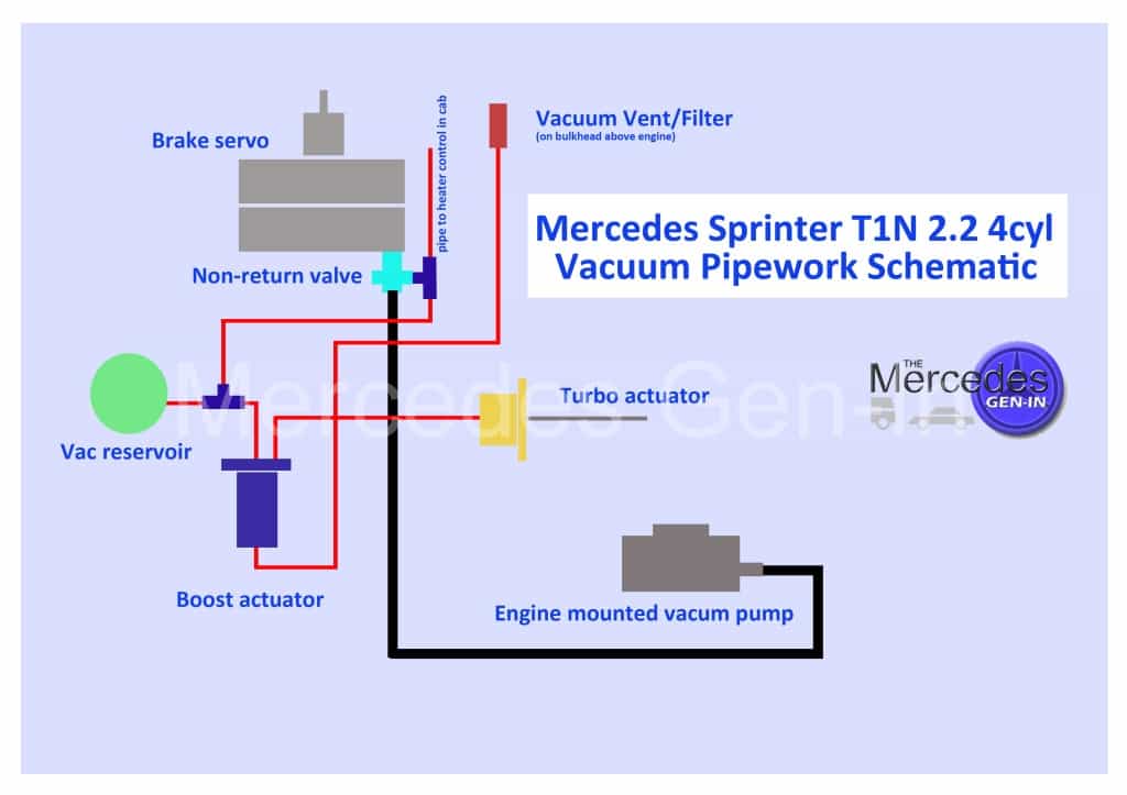
The early Sprinters with vac controlled turbo actuators are quite basic in operation and there are only a few elements to the control loop. These can all be checked out systematically and the faulty element identified and replaced/repaired.
Let me try and explain in basic terms how the turbo control system works so that you may get a better understanding of what is going on:
VNT Turbo and Vacuum Actuator (sometimes known as a VGT Turbo)

Sprinter Vacuum Boost Actuator
The turbo itself is a Garrett VNT variable vane turbo, the details of which you will find elsewhere on this site. ( http://www.mercedes.gen.in/WP35/diesel-mercedes-sprinter-turbo-rebuild/ ) It is controlled by a vacuum actuator that moves a set of mechanical vanes within the turbo to vary the turbo charge rate – there is no conventional dump valve on these turbos and many times you will wrongly read people refer to it as the ‘dump valve actuator’. The charge actuator resides bolted to the turbo body on an extended bracket, its push rod connects to a small lever that enters into the turbo body casting, moving a small lever shaped rather like a dog-bone. This lever engages in an annular ring that in turn interlaces with a set of similar levers attached to each variable vane. A single action of pushing or pulling the actuator rod moves all the vanes inside the turbo in unison, developing more or less turbo charge dependant on its position. Inspect the external lever that the actuator push rod attaches to, ensure this moves smoothly as you accelerate / rev the engine. Look for any misalignment of the lever throughout its stroke as it passes through the turbo body, as the bearing surfaces on this shaft can wear or oval allowing the internal lever to ride over the annular ring inside resultantly not moving any of the vanes. A quick and dirty test to indicate any problems with the variable vanes is to remove the air box or air filter housing and listen as the engine is revved. Once the engine is started, the vac actuator rod should move down slowly as vac builds, this in turn should apply force to the lever moving the vanes into a fully charged position. As you rev the engine you should hear a very loud and strong tornado type howl from the air box, if you do not, and the actuator has moved pulling the lever downward there is a chance that the turbo itself is faulty. Normal operation is as follows. Stationary engine, rod fully extended, vanes in no charge position. Start engine, rod pulls lever downward slowly, vanes full charge position. Rev engine, rod moves in and out during the rev cycle, vanes apply variable charge through rev cycle – Audible howl from air box.
Turbo Actuator Electric Vacuum Control Valve

Sprinter Boost Actuator Valve
If the vacuum actuator is not pulling down once the engine is started check for vac at the pipe, if vac is present, the actuator could be seized or faulty (internal diaphragm split) rectify this. If you follow the vac pipe back from the turbo you will see that it goes to an actuator that is bracket mounted on the inner wing below the air box at the back of the off side headlamp (UK Vehicles) This can be pulled upward off its bracket mounting rubber and moved to a better place for visual inspection. This electrical valve actuator is popularly at fault with the Mercedes Sprinter model and your dealer will have sold hundreds of this item over time. It has a single two wire electrical plug connected to it and three rubber pipes; in some cases its pipe locations are even marked: IN – OUT – VENT. Check vac supply to this device observing and rectifying any split or leaking pipework. Once good vacuum supply has been determined, with the ignition off (no power to the valve and no vacuum present) the route of vacuum should be blocked by the valve to the turbo actuator. The turbo actuator supply pipe should be vented to atmosphere via the electric control valve to a small filter (looks like in-line fuel filter) mounted above the engine and sitting by the side of the brake servo.
Turning on the ignition places a constant 12v to the electrical controlled vac actuator valve, (This voltage pulses during normal engine operation) vac should now be routed from actuator valve inlet to the turbo actuator (outlet) and the vent should now be blocked. Vacuum switching can be verified by using a hand vac pump (Mytivac or similar) Simply sucking on the pipes will not prove anything, as there is an internally sprung pressure control diaphragm inside the electronic valve so that operation will not occur until sufficient vac is present – the only thing you will achieve by sucking with your mouth – is a red face! An old Mercedes engineer once shared that there are two versions of the electric vacuum valve available, one with a blue cap and the other with a black cap, only the matching type should be used as a replacement. I cannot verify this information as I have only ever seen the black cap type, but best practice would suggest replacing the unit only with the correct version to be 100% on the safe side.
Relevant Service Manual Extract View Here
ECU Control
The ECU control loop circuit is quite simple for turbo actuation. The electric vac valve is controlled by simply switching the 12v supply on and off by the ECU, this is called PWM or Pulse Width Modulation – it’s easy to test this control voltage is present with a volt meter at the valve electrical plug/connector with ignition on. If no control voltage is present look for a break in the wiring from the valve to the ECU. Trace back the wires to the ECU connector and prove continuity exists from the ECU connector to the valve. Pin outs and wire colours are given in the included diagrams. There has been commonly reported breaks in the valve supply wiring as it is routed in front of the intercooler behind the grille and also in the area of the near side headlamp where the loom kinks back into the engine bay around the radiator. The wire colours to look for here are white and blue (on my model) but please check the included diagram/chart for correct model notation.
Relevant Service Manual Extract View Here – Wiring Identification at ECU – Turbo Boost
ECU General
Remove the ECU from its slide tray under the passenger dash area beneath the glove box area. It is quite common for the bulkhead grommet to displace where the main ECU loom is routed to the engine bay allowing water to enter and run down onto the ECU connectors. Remove all the connector attachments to the ECU and check for pin corrosion, if this exists clean up both the pin and connectors as best you can. Importantly – reseat the bulkhead grommet.
Charge Pressure Sensor / Intake Air Temperature Sensor

Sprinter Boost Pressure Sensor Location
There are two sensors in the control loop, a pressure sensor and an air temperature sensor. They are identified as one having three or sometimes four wires (commonly three) this is the charge pressure sensor. The second is intake air temperature sensor having two wires. They are both located in the upper section of the intercooler discharge hose, on the near side of the vehicle (UK versions) on the hard moulded plastic section of ductwork before the final supply hose to the inlet manifold, just to the side of the radiator. The pressure sensor is attached to the housing with two small bolts. The connections to this device are again simple to understand and test. One of the three wires is ground, the second is 5v+ve supply and the other connection gives an approximate variable voltage output +0.2v to +5v referenced to ground dependant on charge pressure. The other sensor (air temperature) is found slightly lower down the plastic section of pipework, this measures charge intake air temperature. This has a two wire connection that is connected across an internal thermistor bead that feeds back a change in resistance value relative to air temperature inside the inlet pipework, the two connected wires are fed through the bulkhead, directly back to the ECU along with those from the pressure sensor. The temperature sensor should measure between 400 and 500 Kilo-Ohms out of circuit. In the information given it is possible to plot the output from the charge pressure sensor to give an indication of charge pressure in the system, from this you can derive if it functioning correctly or if to suspect it as faulty. If you need to measure what is going on in-circuit without disconnecting these components, take a number of drapery pins and push them through the insulation into the conductor cores of the required wires thus allowing you to connect a test meter and take measurements without the need to disconnect or cut any wires.
Relevant Service Manual Extract View Here – Sprinter Boost Pressure Sensor
You can disconnect any of these components without lighting the EML warning lamp as no indication of a fault is given by the removal of any of these components from circuit. That is why the dreaded turbo limp home fault often occurs without any indication on the dashboard.
Rev Limiter Function
Normally Sprinter engine revs are ECU limited whilst stationary to around 3500 rpm. Depressing the clutch and then further releasing it should now allow revs to increase above this range to the rev limit. If there is a limp home fault, engine revs will not progress above 3000 rpm even when dipping/releasing the clutch when stationary. Once the fault is rectified the rev range and limiter function as described above will return to normal. It is a good idea to check out both of the necessary brake and clutch pedal position switch sensors (on the pedal box above the clutch and brake) and where possible always get hold of a compatible diagnostic code reader as often faults are stored and not indicated with a EML lamp.
I hope this helps you to better understand the function of the turbo boost circuit on early model Mercedes Sprinters and that it assists you to fault find and rectify any problems you may have.