From time to time you come across things that just amaze you, and this customers Mercedes Sprinter van was no exception. The van had come in with an obvious ABS fault, sensor wire physically and visually broken, and no warning illumination on the dash. Once the ECU was read there were in fact several faults related to the engine that should have illuminated the EDC lamp too, but nothing!
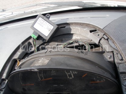
After a bit of fuse-chasing and voltage checking, it seemed the problem was at the instrument pod end. It turned out the previous owner had removed the instrument pod, unclipped the PCB and prized it apart just enough to slide a small screwdriver in and break off the surface mount indicator LEDs. These should have illuminated showing the current faults. It was hard to say if this was actually a measure to disguise the faults so the vehicle could be sold, through maybe auction or otherwise or if it was a desperate attempt to get the vehicle through the annual MOT – Who knows… All I knew was that before any other remedial work could be done this sensibly had to be rectified first.
To gain access to the Sprinter instrument pod, first prize off the light grey facia moulding that contains the drivers air vent and switch banks. Tilt this around the steering wheel and let it hang to the floor with switch cables still attached. If you have more options and switches in place on both sides of the steering wheel it is best to label each and remove the electrical connectors from the switch backs, removing the panel completely. Do not be tempted to not mark what comes or goes to where, as several of the switch options have the same plug shape format with only different pin layouts. It is entirely possible you can plug the wrong loom plug into the wrong switch as they will fit!
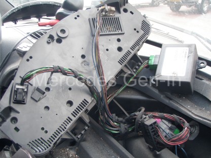
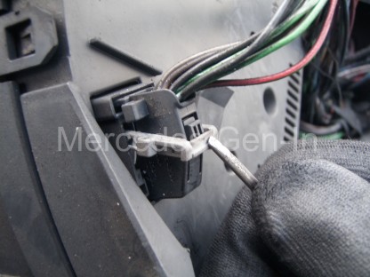
The removal of the facia reveals two screws either side of the instrument cover, these can be removed and the instrument cover lifted off and out of the way. A further two screws either side of the instrument cluster hold it in place and once removed the assembly can be pulled forward from the top, disengaging it completely. On the rear cover of the cluster you will see two multiway connectors, one grey/white one black. These have a special locking latch mechanism that releases them from the PCB. Just behind the lever on the plug body shell is a small press-in latch, once pushed, the locking release arm can be drawn over it and arced downward to horizontal. The action of moving this lever pulls and ejects the connector from its mating part, enabling it to be easily released and fully disconnected from the cluster. Unlatch both connectors and remove the instrument cluster to a clean work surface or bench.
Around the removed instrument cowl is a series of clips, three at the top and bottom and one each side. Carefully unclip and release these, lightly pulling off the front cover of the instrument pod as you go. Once totally free the back cover can also be pulled from the instrument PCB.
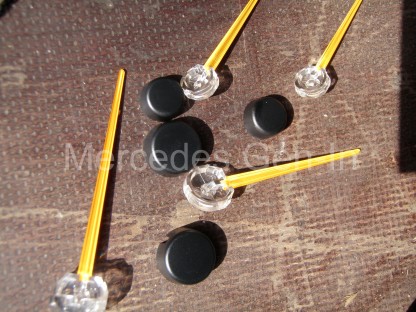
To gain access to the LED indicator lamps you will need to pull off the dial servo motor indicator fingers. Grasp the centre black covers and unclip them, making note at this point of what came from where. Then grip the indicator pointers by their central hub and ‘pinch’ them off the spindles between forefinger and thumb. Be sure not to rotate the gauge stepper motor spindles as the correct position of the pointer will be lost. This will make repositioning the pointers difficult – without further powering up of the instrument cluster to reset the base zero positions, then agin aligning and refitting the indicator needles to accurately point to their associated rest positions.
Once all pointers are removed, the black instrument face can be removed from the PCB. This is done by unclipping a series of protruding white clips at the back of the board. Once these are released the two parts can be separated, revealing the indicator LEDs at strategic points on the front face of the PCB. Positioned so they illuminate and channel light to backlit icons screen printed on the instrument face.
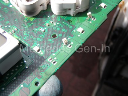
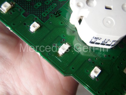
You can see from the photograph above what state the warning indicators were in and how they had been crudely levered/broken from the board. Fortunately only the LED components themselves had been damaged and not the copper tracks where they were attached. All I needed to do was remove the remnants of the old LEDs and attach new replacements.
Please note: – I do have number of new yellow OSRAM SMD ultra-bright LEDs as used in Mercedes Benz consoles and if anyone has similar problems please contact me and I can arrange supply for a modest cost.
If you need to source Mercedes instrument panel LEDs – drop me an email to steve@mercedes.gen.in
Once the new LEDs were soldered in position (fitted to observe the correct diode polarity) the PCB was ready to be reassembled and fitted back into the van. Once reinstalled the ABS fault was rectified and the ECU fault codes cleared. This correctly extinguished the ABS lamps and left the EDC lamp illuminated – correctly warning us of our next engine related problem to be rectified!
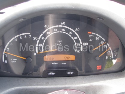
This issue truly highlights the importance of any potential Mercedes purchaser testing all the dash lamps in ‘ignition’ position to make sure all lights are illuminating correctly as they should in ‘lamp test mode’ before starting the vehicle. This point could easily be overlooked when buying a vehicle and turn out to be quite a costly oversight, so as you can see is this is a simple but very important check!


Exalent. Post think I’ve put mine in wrong
Hi Darren,
That is possible, you can always check the polarity by using a test meter on the Ohms range, often the current used to measure ohms by the test meter will just about illuminate the LED with the meter probes touched in one direction, reverse them and it should not light. Compare the light – no light combination with the LED next to the one you have replaced, this will at least confirm if you have the device soldered on in the correct way. Also if you took too long soldering the device to the PCB, heat can damage the LED so badly that it requires replacement. Swift soldering is the key once you know the polarity and way it attaches to the cluster board.
Regards
Steve