Technical MB General

Technical non-specific MB

Mercedes C Class (W203) Alarm Problems

If your Mercedes C Class alarm starts to behave strangely with random false alarms sounding, indicators flashing without any alarm sound or even chirping whilst you are driving, then the number one cause for these issues is the siren module.  The siren module is a round black plastic canister about the size of a small bean can, containing an alarm sounder, control electronics and back up alarm system batteries.  It is these internal NiMH batteries that will start to age and deteriorate, giving rise to the conditions stated above.

Mercedes C Class Siren Sounder Battery Replacement 1

The problem with the batteries is not quite as simple as it sounds.  What happens is they start to leak and spread over the PCB inside the sealed alarm unit.  The electrolyte from these cells is conductive, as it spreads, it bridges circuit tracks and components making the alarm system unstable and causing it to do peculiar things.  A replacement sounder is around £100 from a dealership and once fitted will in the majority of cases, cure any problems you may have.

Mercedes C Class Siren Sounder Battery Replacement 2

The first thing to do is locate and remove the faulty sounder.  On the C Class (W203) it is located behind the plastic protection panel under the left hand (near side UK) front wheel arch.

Simply remove the road wheel, remove the five plastic 10mm nuts and remaining fixings that secure the inner protection panel. Remove it from under the wheel arch.  You should now be able to see the siren, fitted to a steel bracket that is fixed to the bodywork.  The torx self-tapping fixings that hold the siren bracket to the vehicle are security types with the inner peg.  If you don’t have the correct security tool, just tap them round slightly on their outer circumference to loosen with a small chisel or punch, once slack, they will usually remove with firm finger pressure.  The rearmost fixing is a strange 8mm crimped nut affair, that quickly removes with pliers. Once the support bracket is free, the siren can be unplugged and totally removed from the car.

Mercedes C Class Siren Sounder Battery Replacement 3

To replace the siren simply plug in the new unit with the car unlocked and alarm de-activated, re-fix the bracket and build up the inner arch panel. Fitting the wheel and lowering to the ground to complete the job.  If you are doing a straight swap-out with a new component and you have good elevated access, it is possible to replace the siren unit without removing the road wheel – by just undoing the trailing edge fixings of the plastic arch liner and pulling them out of the way while you remove/replace the siren unit.

Replacing the batteries in the siren module / sounder unit

If you have been following this site for a while, you will have probably realised that there is a little more on the subject to come –  there is an option that could save you some money and get your alarm working correctly again, for around a £15 chance investment with some DIY time and a soldering iron.  This style of siren module/unit is fitted to many models of Mercedes vehicles spanning many years and this repair technique is applicable to all instances where this type/style of sounder is used.  If you are interested then read on…

Mercedes C Class Siren Sounder Battery Replacement 4

The first thing to be aware of is that the batteries, as they leak, do start to corrode the PCB within the siren unit, if you do catch this in time (and it really has to be quite bad to be unsuccessful) then you can repair the unit very economically.  If however the PCB has deteriorated ‘just too far’ or there is another fault in the unit, you will have probably wasted your money and time, needing to buy a replacement. If its worth the risk of chancing your luck – that is up to you!  Interestingly, if you can live without any audible alarm at all, then you can just leave the siren unit disconnected and tape up the connector. This has no detrimental effect on the rest of the alarm system or its linked components.  My logic in all this is:  If I can fix it for a few pounds then all well and good, if not then leave it disconnected as £100 dealer charge for new or buying a used unit that is probably almost as bad inside as the one I am removing, albeit at the moment still working, are not in this case acceptable options. Equally a customer may decide that the cost to repair a sounder on an older vehicle is just not worth it – so you can just leave it disconnected!

Mercedes C Class Siren Sounder Battery Replacement 5

If you decide to have a go at changing the batteries you will need to remove the sounder from its bracket, again a single security torx fixing is the order of the day. Once this is removed the sounder can be cut open.  It is ‘weather-sealed’ and the only way to get it open is to cut carefully around the seam with a junior hacksaw, rotating the sounder as you go.  Do not allow the blade to penetrate deeper than half its width, as if you cut too far inside you may damage the PCB or sounder wiring.  Once the cut is continuous around the siren unit, pull apart the two halves.  The front part will contain all the electronics with sounder, the rear is just a shell cover with an aperture for the electrical connector pins.

Mercedes C Class Siren Sounder Battery Replacement 5

Unclip the sounder plug, pink and white wires inside and unclip the PCB pulling it off its two locating pegs.  It should now be out of the plastic body and you will be able to get a full visual idea of how bad the PCB has been damaged by the battery leakage.  The one pictured is quite bad and to be honest if it was any worse than this I would not go further, so in this instance it was a borderline repair, reducing my odds of it all working out successfully due to the poor condition.

Mercedes C Class Siren Sounder Battery Replacement 7

Note how the batteries are polarised, take a photo so you can be sure you are fitting the new NiCd’s with their correct polarity as once you get cleaning, often the markings on the PCB also get removed.  Using side cutters clip off the old batteries flush with the soldered holes and throw them away.  Using a soldering iron heat the remaining part of the battery pin until the solder melts fully, then quickly bang the PCB onto a cardboard box.  This shocks the molten solder and pin from the board and should leave you with clean holes for the new battery contact pins.  Repeat on all eight holes.

Mercedes C Class Siren Sounder Battery Replacement 8

Now you have the board clear, use PCB flux cleaner spray or other electronic solvent to scrub away the electrolyte that has leaked from the batteries, use an old tooth brush and lollypop stick to scrape the most stubborn material away. You can now get an idea if the battery juices have eaten into the copper track, if it passes inspection, continue cleaning the circuit board with an abrasive pad, I used one similar to those used to clean model railway tracks.  Eventually it should look like the photograph.

Mercedes C Class Siren Sounder Battery Replacement 9

You will need to purchase a pair of replacement batteries from a Maplin store or other electronic component outlet, they are quite a common 3.6v 140 to 160 mAh NiMH cell pack, measuring approximately 24mm x17mm x 15mm  The only issue the replacement batteries have is that the component legs on one side will need slight modification to fit the PCB but apart from that they are drop in replacements. The batteries cost in the order of £7.50 each. Part Number BN-24B

Mercedes C Class Siren Sounder Battery Replacement 10

Once you are satisfied with your cleaning, bend up the single mounting leg/tab of each battery into  a ‘U’ shape as you can see in the photographs.  Fit and solder the twin-tab side of the battery to the PCB, observing the correct polarity.  Once you have this side soldered in, cut a short length of thin stripped wire or tinned copper wire if you have it.  Using a small piece of cardboard packing under the edge of the battery solder one end of the stripped wire into the PCB.  Now loop it over the ‘U’ shape you have formed on the battery tag, threading it back into the board. Pull the wire tightly and solder the remaining end to the board.  Now heat and solder bond the wire to the bent tag as it passes through its formed ‘U’ slot. Clip off any protruding wire from the back of the PCB

Mercedes C Class Siren Sounder Battery Replacement 11

Fit both batteries and check your work for solder bridges etc.  Once you are happy, mask off the siren sounder plug and three prong external connector pins.  Spray the complete electronic board with clear lacquer, both sides and allow to dry thoroughly.  Once dry, refit the electronics to the front section of the siren unit. Connect the red and pink wires to the sounder unit then run a continuious bead of silicone sealer or epoxy resin around the plastic seam of the housing.  Offer up the rear plastic housing section and press it into position.

Mercedes C Class Siren Sounder Battery Replacement 12

Clamp the assembled sounder/siren unit in a vice gently until the silicone/epoxy as hardened. Then for good measure, although really not necessary, tape around the seam joint with insulation tape making a tight secondary water resistant seal.

Mercedes C Class Siren Sounder Battery Replacement 14

You can now refit the rebuilt unit to the car and test your work, either it will work perfectly or your time has been wasted!  If successful then you have saved yourself  a wedge of money, if it does not work then you have wasted £15 and can just leave it disconnected or go out and buy a new one – the choice is yours!

Hopefully all will be well and your Mercedes will once again have a fully functional alarm.


Mercedes Vito (W639) Front Brake Pad Sensor Replacement – Video

Some time back the brake caliper on the drivers side of the Mercedes Vito (W639) was giving trouble. It was sticking badly and as a result stuck on one day to the extent that generated hear melted the brake pad warning sensor.  Obviously I dealt with the sticking caliper but at the time I did not have a replacement sensor to hand so I joined the two ends of the remaining wires just to extinguish the warning lamp on the dash.  To read how the sticking brake caliper was repaired read here.

Mercedes Vito W639 Brake Pad sensor Replacement


It was a nice afternoon and I had little else to do, so I decided to fit the sensor that I had purchased from the Motor factors as a replacement for the ‘work-round’ but so far had not had the chance to fit it – Ideal play day job!  The part was just under £4.00 from the motor factors, with an OEM part number of 906 540 15 17 or  a VTECH aftermarket part code of  649ME0130 – should you wish to order one.  Interestingly, you often get a pair of sensors with a new set of brake pads but if you choose Mercedes parts you have to additionally purchase the sensors individually. 🙂

Mercedes Vito W639 Brake Pad sensor Replacement 1

I must point out that if you do get a light on the dash, warning you of low brake pad thickness, please investigate it, as its probably warning you of the actual wear condition and not a faulty sensor like in the case investigated here. (I knew it was a faulty sensor, so ignored the light for a few weeks!)

The warning light on the dash does extinguish automatically once the faulty sensor is replaced, simply by cycling the ignition.  In the video I use the Autel Maxidiag code reading diagnostic tool to investigate if the fault is stored at ECU level and how the effects of clearing the logged fault with the diagnostic tool resets the dash warning lamp.  Interestingly even once the fault code is cleared (Key in – engine on), the dash lamp remains illuminated until the ignition is cycled, unlike the majority of cleared engine fault codes that immediately extinguish the warning lamp when actioned by the diagnostic tool, either engine running or static with ignition on.  Watch the video, its simple stuff but there is some interesting commentary if the job is new to you.

Replacement of this sensor is quite simple, all you have to do is remove the road wheel and remove the brake caliper as if changing the pads.  Once the caliper is removed, slip out the outboard pad and install the sensor in the provided cut out on the steel backing of the brake pad lining.  Thread the sensor connector through the access hole in the caliper as you reassemble it. When the slide bolts are in position and tightened, plug in the pad sensor to the mating part that is bolted to the brake carrier assembly.  Replace the road wheel and cycle the ignition.  I hope you find this of some use.

Mercedes Vito W639 Brake Pad sensor Replacement 2

Purchasing a used Mercedes Sprinter diesel engine.


For whatever reason you may be looking to purchase a used replacement engine, there are quite a lot of pitfalls that you may fall foul of if unaware. I hope to highlight some of the things to look for and be aware of when searching for that ‘mechanical bargain’ in the small ads or breakers yard.  Indeed this guide could be used to assist you if you were about to purchase a used van and needed to know/check a few things out indicating the condition of the engine before you buy.

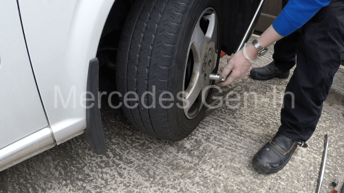
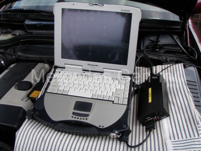
Probably the most obvious thing is, ‘can you hear the engine start and run’?  Without doubt this is the best way to buy a used engine. Quite often engines may be removed from a scrap vehicle and sold on this basis.  They will frequently be strapped to a pallet or resting on an old tyre waiting for sale and although there is little you can do about that, there is a few things you can check to be more positive about your potential purchase – especially as you will not be able to hear it run!  Don’t forget to take along your torch on any reccy’ as you will need this for most of your checks.

If you do get chance to inspect an engine while it is still in the vehicle, make a mental note of the mileage and ask questions of the seller – even before you lift the hood/bonnet or turn the key. It goes without saying the reason for the sale should be credible, if the rest of the van looks good, one would ask why the engine was being sold – is it stolen and being parted-out?  Just be aware.

Sprinter used engine inspection

Always better to hear a used engine running if possible

If the registration plate is still there make a note of this too, along with any vin number.  The purpose of this is to have all the information to hand if you need to later double check if the engine is compatible with your vehicle, these are the details that a dealer or independent will need to cross check the parts on his system to confirm compatibility with your own vehicle if you are in any way uncertain.

Have a quick look at the engine in situ, dip the oil and look into the coolant expansion tank – it is that the vehicle was front ended, the radiator will likley be broken and there will be nothing to look for in here, but have a look anyway.  It should be clean inside with no frothy oily mess and should not be coated with thick brown rusty sludge.

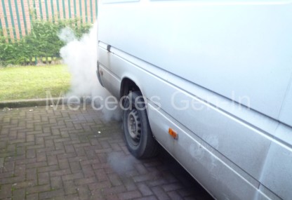
As with any other vehicle purchase if you can, you will want to hear it run from cold. It should start without hesitation and soon settle into an even idle.  Try and gauge if it is as quiet as your own engine was when it was working properly.  If there is no coolant, you will not be able to run it for long so quickly pull of the breather hose from the oil separator or turbo intake pipe and look for smoke and pressure here, if either is excessive walk away.  This is an indication of worn bores and/or piston rings and really not what you want to be buying into.  You can look for fumes and blow-by pressure at the dipstick tube also, but this is not always as conclusive as what can be seen at the breather pipe.

Can you here the turbo spool up?  If you are in doubt remove the air cleaner cover or intake hose to the turbo body and dab the throttle.  You should hear a healthy howl if everything is working correctly.  Glance back to rear of the vehicle as you rev the engine and make sure you can still see the sky!

Below is a checklist to help you assess your potential ‘running’ or ‘palletised’ engine purchase, some items in this list may/may not apply:

Coolant Expansion Tank (Front right hand side slam panel area)

Should be clean inside, no brown sludge, no oily mayonnaise. With the engine cold and running, carefully remove the filler cap and place your hand over the coolant reserve neck, get an assistant to blip the throttle, there should be no pressure to lift your palm off the lip.  Have a quick glance inside – no bubbles is good.  Problems here could indicate a potential head gasket issue.

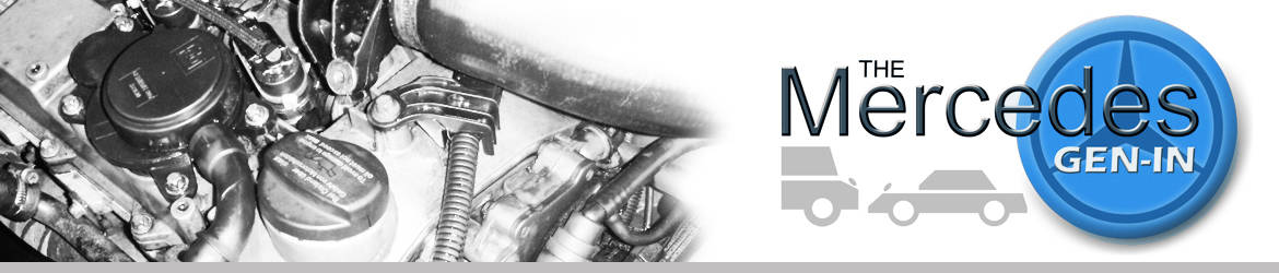
Oil Separator (Top of engine behind oil filler cap)

While it is normal for a high miles engine to be a little ‘wet’ with oil around this area, any white smoke or fumes beyond the ‘barely visible’ from the vent pipe that runs to the turbo inlet could signify worn bores and/or piston rings.  Pull the pipe from either end and observe to be sure. Do not be too concerned by traces of oil here and also if the pipe is gummed with a little mayonnaise as in many cases this is normal.

Check the crank case pressure - inspect the oil separator pipework

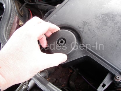
Check for excess crank case pressure – inspect the oil separator pipework

Water vapour, moisture and condensation escape from the crank case and exit here to the turbo inlet.  The device that is present on the lower pipe is not a sensor it is a small heater! This actually stops moisture and crank case water vapour freezing in the vent pipe in colder climates, blocking it.

Oil Dip-Stick

Pull this and check the oil level, there is not much to be told from the black oil that will be on the end but caution must be observed if there is any water droplets, froth or whitish deposits on the stick. As with the coolant tank inspection any issue here could mean that the head gasket may be suspected as leaking.  Any obvious quantity of water in here could also mean that the oil cooler fixed to the side of the oil filter housing is passing pressurised water into the engine – not good. There should be little or no pressure, or smoking from the open dip stick tube.

Oil Filler Cap

Pretty much the same visual inspection applies as above. Do not remove the oil filler cap with the engine running – you will have an ‘oil-shower’, as the duplex timing chain runs directly beneath the cap.  If there is a lot of oil around the filler cap it is not unusual for the cap-lip to be slightly split, allowing oil to pass out onto the rocker cover and run down the left of the engine finding its way onto and into the alternator!

mercedes filler cap

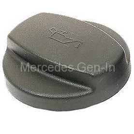
If there is oil around the filler look for a split plastic filler cap on the lip – Simple fix

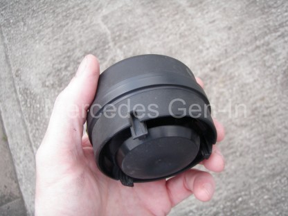
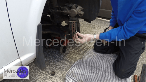
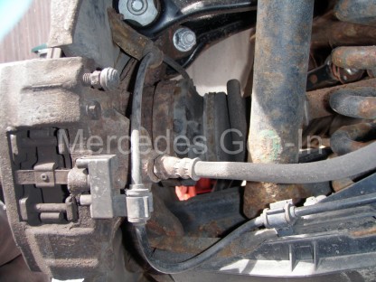
Leaks – Visual Inspection

Start from underneath with your torch, you will not need to jack the vehicle, just slide under and look under the front bumper.  Places with oil staining and dripping will be very easy to spot. While most oil leaks can be fixed, there are some cost implications to be considered depending on what and where the leak is.  A leak around the crank pulley for example will mean it will have to be removed and a new seal fitted, often if this has been leaking for a while the harmonic  damper pulley (if fitted) may have suffered deterioration due to the oil. (See Harmonic Damper Pulley in the check list)  Oil may be leaking from the rocker cover, do not assume this will be a simple fix, if it is going to be a problem all the injectors have to be extracted to remove the cover and replace this gasket, doing so can sometimes open a whole can of worms (Injector removal and so on). Lots of oil around the turbo body is not a good sign, it should be reasonably dry and in most cases the iron casting should remain red rusty.  Look beneath the turbo and seek out where the turbo oil return pipe enters on the sump line.  This could be oily, contaminating the surrounding area, indicating the oil return pipe seal requires replacement.  (two gallons a min. circulate through here!) The turbo/manifold has to be removed to replace this commonly failing seal.

O ring seals are simple to replace to cure oil leaks on the Sprinter HP Diesel and Vac pump bodies

O ring seals are simple to replace to cure oil leaks on the HP Diesel and Vac pump bodies

Oil leaking from the area behind the vac pump (or diesel HP pump for that matter) and running down the face of the engine block are usually a simple fix. In each case this is a large diameter ‘O ring’ that seals against the block and is simple to rectify.  Any diesel leaks should be investigated carefully and if found to be from the high pressure diesel pump (triangular shaped pump block on the front of the engine) head casting seams could indicate new seals or pump are required – not a cheap fix for a replacement pump. (It is worth noting to make sure the viscous fan central hex bolt is free and not seized before any engine installation, as this could hamper future diesel pump work)

Look also at the joint between the gearbox bell housing and the rear of the engine, any serious black engine oil presence here could indicate a crankshaft rear seal that is weeping.  Not a huge job to do when the engine is out but best avoided if at all possible, certainly another tick or cross when you are debating your offer price.

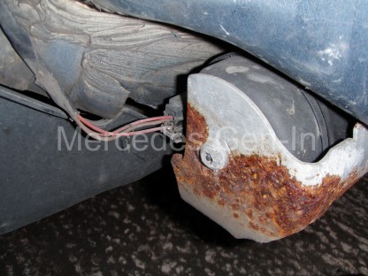
Water leaks should be easy to spot, especially if antifreeze is present in the system.  It will leave tell-tale staining in the form of a coloured salty scale.  Look at the water pump behind and up from the crank pulley there is a tiny hole in the pump casting nose, any staining or wetness here could mean the pump seal is failing and will be due for unit replacement.  Obviously hoses are an easy fix if leaking and should be all checked before putting the engine into service in your own vehicle.  Importantly include the small bypass hose at the rear of the block RHS above the starter motor area, this is a nightmare to replace once the engine is in situ due to poor access.

Noted leaks from any diesel related item or component must be investigated as these could be costly to rectify. (See Injectors Injector Cover in the checklist)

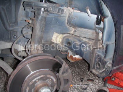
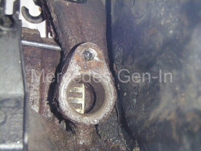
Harmonic Damper Pulley – Crank Pulley

While not a major issue to rectify if found to be suspect, it is worth checking the harmonic damper/crankshaft pulley that lives at the bottom front of the engine – it drives all the belts and is the main pulley from the motor crankshaft.  This is made in two mating parts, bonded together with a rubber metalastic material that is designed to absorb crankshaft borne detonation pulses, reducing noise and vibration of the running engine.

Sprinter engine inspection guide

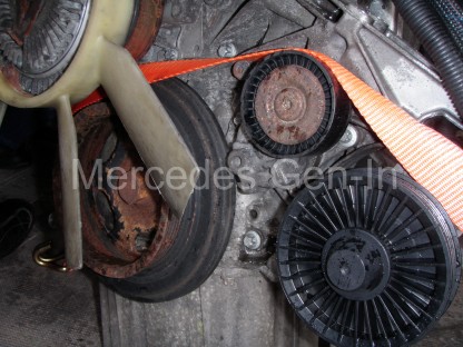
Pulley and idlers are worth a look

What happens over time is the rubber sandwich deteriorates (often through oil contamination) and the two pieces begin to part company.  When things have got quite bad, the pulley begins to make a ‘clacking’ sound as it rotates (usually people tend to think its a far greater internal engine problem, as it can get very loud indeed) It is actually the pulley edge catching on the crankcase as it revolves. Its presence can sometimes occur only under load as the pulley flexes it can be hard to spot.  Look at the pulley with your torch and identify the rubber seam circumference, if it looks tired and cracked then budget to replace this before you refit the engine as failure can result in expensive engine damage. In itself not a full diagnosis, but you can also try to gently pry bar the edge of the pulley away from the block to get an indication of any detrimental flexing that may be present.

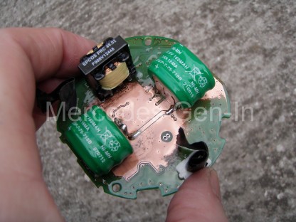
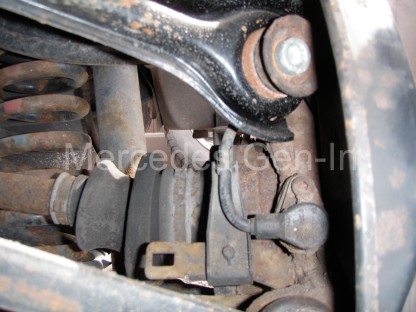
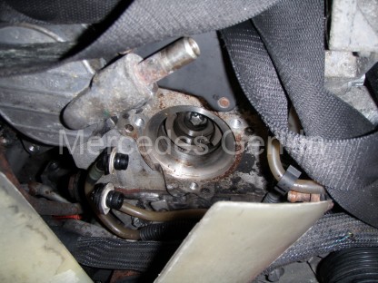
Injector Cover – Injectors

This is probably the most important check that you will do and will be the most awkward, both from the point of view of asking the seller if you can take a few parts off to inspect it and also from the point of view it will take you about 20 mins to complete.  What I would do is leave this as the final ‘deal breaker’.  If you are happy with what you see, agree with the vendor a price on the proviso the injector inspection proves satisfactory and explain that without this inspection you are not interested, whatsoever – This is actually very true, as if overlooked and bought blind, the engine could land you with a bill approaching and exceeding what you have just paid for the complete engine!  Of course if the injector cover is not fitted or missing further inspection is easy and far less of an issue for all.

Sprinter used engine inspection

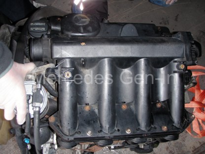
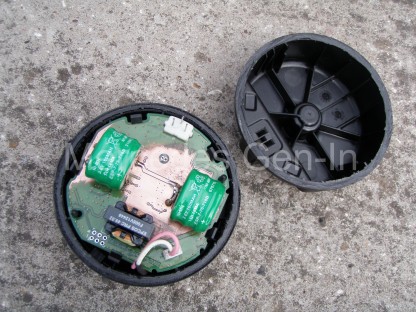
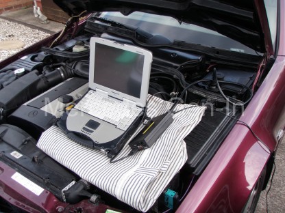
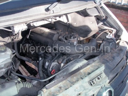
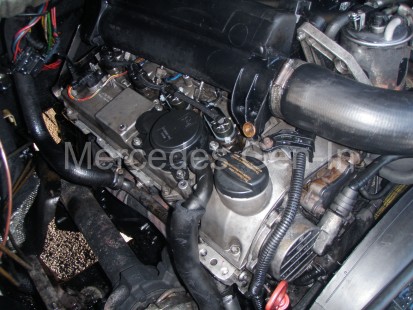
This looks a great clean engine…

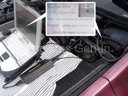
Having agreed your ‘investigation’, you will need four tools. A flat blade screwdriver, reverse torx socket wrench or a 10mm/8mm ring spanner and a 5mm hexagon key. Undo the turbo inlet hose from the inlet manifold and tuck it out of the way.  Undo the 8x torx pins holding the top of the inlet manifold to its lower section, remove the single pin at the front near the fuel filter and the rear fixing pin behind the plastic manifold, on the top left looking in, just sneaking under the bulkhead. (This one is often not fitted/missing as it is a PITA to get at – again a measure of lesser quality servicing maybe!) Lift off the upper inlet manifold section. This will reveal the 6x injector cover hex cap-screw fixings.  Once these are removed, lift up-and-off the injector cover.  If it makes a ‘crispy crunchy’ noise as you begin to lift it away, you could almost refit it at this point and just walk away!  Once you have the cover removed all should look fairly clean and oil free under there.  Be aware the oil separator may have deposited a little oil around the adjacent area but the overall appearance should be clean and dry. Any black carbonous coal like substance and you will have some work to do.  This condition signifies the injector seals have failed on one or more injectors and will need to be replaced, as combustion gasses are blowing-by the injector seats/seals and depositing carbon waste on the engine surface.  The common name given in the trade to this condition is: ‘Black-Death’.

OLYMPUS DIGITAL CAMERA

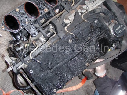
Mmmmm maybe its worth less than I first thought! A bad case of Black-Death… It should look like the first image at the top of this post.

The presence of any Black-Death around the injectors will and should drastically effect your offer price downward. This job is known to be very difficult to price, as issues encountered along the way could range from injectors that cannot be removed, stripped hold down clamp bolts and deep cut sealing seats in the head pockets due to passing exhaust gasses. Each extra issue encountered, over and above normal labour cost, will soon double or treble the overall cost of repair and caution should be heeded when making your offer.  Be sure to make your bid based on a worst case scenario.  There is plenty to read on this subject both here on Gen-In and on the web, just Google it and learn what you need to know.

If the vendor does not understand the issue you have uncovered, then simply look elsewhere, at least safe in the knowledge your decision was made wisely and with due diligence.  Overlooking to check here can cost you dearly! Look at the engine above that otherwise looked a very good buy indeed.  You have been warned.

Sound and Vision

Satisfy yourself that the engine sounds good (if you get chance to run it) and that there is no knocking or tapping noises over and above the normal engine song.  Any metallic ‘Brrrrap’ possibly from a little end heard under a throttle blip, or heavy knocking noticed under load or overrun, then leave well alone and look else where.

Place your hand over the exhaust at idle and feel the regular pulses from the exhaust, if irregular there is a chance you have a slight misfire at idle and this may need work in the future.  Poke your fingers up the exhaust pipe and wipe around, hopefully this is dry sooty-black.  If its ‘sticky’ or ‘oily’ this is probably an indication of water or oil passing through the exhaust and in my view  would be best avoided.  Look at the emitted gasses from the exhaust – all but for a slight whiff of black soot, visible on a sharp jab of the throttle is good.

Sprinter turbo blown

You don’t want oily smoke like this… Blown turbo in this case.

Any white smoke, as severely shown above indicates oil presence – worn engine or turbo.  White smoke that ‘magically disappears’ or dissipates quickly is likely water from a suspect head gasket.  Listen to the auxiliary belt as the engine idles, is it flapping around? Look at how it runs over the pulleys, is it straight or canted over? If not running true or overly noisy this could signify worn idlers or failing belt tension device. Check to see all the pulleys on the drive belt route are true and not wobbling, indicating worn bearings that will soon need replacement.

Sprinter serpentine belt

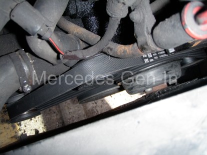
Check belts for flapping, running true especially round the harmonic damper/ crank pulley – this could indicate de-lamination

When you turn off the engine it should stop without fuss, any clicking or snapping, cracking noise could indicate that the ‘sprag-clutch’ on the alternator pulley is failing.  Turn the serpentine auxiliary belt over with your fingers, if its cracked or worn it is usually a good indication the van has not been regularly serviced as this would have been changed under the maintenance regime.

Sprinter Serpentine belt - worn

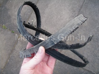
As a rule of thumb an auxiliary belt in this condition is an indicator of poor servicing.

Similarly the age and appearance of the fuel filter canister often gives away the lack of recent servicing.  Overall you should be happy that the engine appears to reflect its mileage – remember you are not buying new and its unlikely that it is going to be perfect. It is mainly all about minimising your risk and getting the best deal you can without spending a fortune on rectifying a catalogue of unknown problems even before you get to grafting the replacement engine to your own transport.

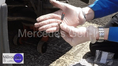
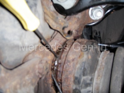
Turn It Over Beethoven…

It goes without saying if you are buying a ‘static engine’ out of the vehicle, do make sure it turns over by rotating the flywheel, a simple thing to do but often forgotten in the heat of the moment – who knows how long the unit has been standing?

Mercedes sprinter used engine buying

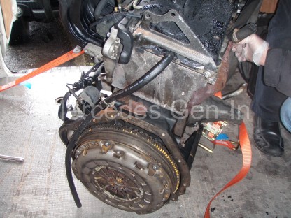
Turn the engine over a couple of rotations to make sure its all free

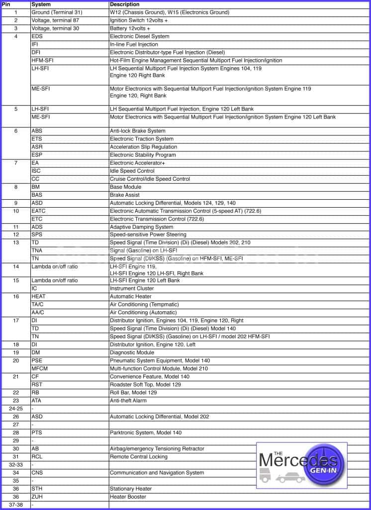
Electrical Loom – Model Year to 2006

If the engine has had its loom cut – often the scrap dealer considers just the engine to be of value and not the ancillaries – be prepared to negotiate your price down a little as its a time consuming job to swap your existing loom over to the replacement engine.  I had a replacement engine come in that was ‘loom-cut’ about the point where it passes across the left hand engine mount.  On this occasion I chose to cut our own existing loom section and solder/heat-shrink the individual wires to the ‘new’ engine to make up a serviceable loom. There were sixty wires or more to deal with, although time consuming it is possible, noting a few important provisos I discovered along the way when carrying out this task.

-1 Wire thickness is important when choosing your colour match – there are often pairs of wires sharing the same colour code and tracers only decernable from each other by their relative thickness. Make sure you get this correct,

-2 The ‘Twisted Thicker’ pairs of cables are injector cables and share the same colours as other conductors.  Make sure you keep the twisted pairs together when joining.

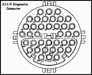
-3 There are two identical ‘Black with Yellow Tracer’ wires in the loom bundle at this point. One goes to the starter motor solenoid, the other to Glow Plug No.2  Make sure you meter these wires out and ensure you have continuity to the correct points.  The Starter cable goes back to the grey ECU connector and the other glow plug supply should route to the glow plug module loom connector.  Just make doubly sure these two Black/Yellow wires that are of identical gauge are joined and routed to the correct point or the vehicle will not have a start signal to the starter.  If after the rebuild you suspect this may have been overlooked as the starter does not spin, its an easy check to test continuity between the starter solenoid cable ring tag to the glow plug module supply. If it bells out then you will have to split the loom and swap over the two black with yellow tracer cables – a good reason to double check this in the first instance!

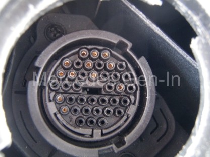
-4 If your purchased engine has its loom in place you should at least give the ECU connector plugs a once-over, as if its been standing outside for any length of time moisture may have begun to work its evil on the fine connections to the brain of the vehicle.  If these look good thats great, but worthwhile treating them to a squirt of switch cleaner and moisture repellant before locking them home in the ECU.

And just before you hand over your cash…

Hopefully the above has given you a little insider knowledge to be able to assess wether the used engine you are considering is worth what the seller is asking and that you factor in any remedial work into your repair budget before ‘splashing the cash’.  There are undoubtably some bargains to be had out there, equally there are also rogues who know the full nature of the faults/condition of their engines, looking for a fast return.

Always try and get a written warranty of some sort for the engine where possible, at least one that covers it running without issue when fitted.  If you are buying from a local source maybe ‘in the trade’ and they are reputable, it is worth an extra few dollars/pounds over a private sale to have the security of even a one month warranty – It is worth remembering too that although your extra labour costs would be lost in any claim, removing and returning the faulty engine – often its better to secure the return (at least a large proportion) of your hard earned than not.

I am sure the opportunity to purchase from a private buyer will crop up and the normal ‘caveat emptor’ rules apply but with careful inspection and honest pricing, taking into consideration any faults noted, there are bargains to had from genuine people.  Just remember, minimise your risk as much as possible by using care and vigilance – knowledge is power!

Obviously this has not covered every single check-point or eventuality, but it at least prepares you for what you may find on your mission! I hope that it has at least helped you out a little.

Mercedes SL (R129) ETS and ABS Fault Light Illumination – Diagnosis

I started up the Mercedes SL (R129) and reversed it out of the drive and as I straightened up to drive forward both the ETS and ABS amber lamps illuminated on the dashboard. This was shortly after completing the front road spring swap posted earlier on this site.

Mercedes SL (R129) ABS fault

Apart from indicating more work to do, I began to wonder if I had disturbed anything when I had replaced the front springs or even earlier, the suspension top mounts.  I went about my business on that day driving the car with the fault lights illuminated, they would pop straight on as soon as the key was turned and would not clear down on any number of engine re-starts.  I had noticed disappointingly, that I had also lost 5th gear (5 speed version of the 1996 R125 with electronic control overdrive gear) and also cruise control operation.  This underlined it was a speed signal fault but I would have to investigate further to narrow the field.

Mercedes SL (R129) ABS fault 1

Mercedes SL (R129) ABS fault 2

I connected the car to my Carsoft code reader kit.  This vehicle being the 1996 model SL it had the Mercedes proprietary diagnostic communication system, accessed from the 38 pin diagnostic socket inside the ECU box next to the bulkhead (firewall).  You can read more about early MB diagnostic systems in this post.  The first read of the ABS system revealed a recorded fault code with the rear left wheel speed sensor (C1106). Rear wheel sensor plausibility.

Mercedes SL (R129) ABS fault 3

On removing the road wheel and checking the cable routing, all looked well. Often the older series of Bosch wheel speed sensors have a habit of collecting large amounts of iron debris on the sensing tip over time, causing impulse read issues at low speeds.  This was in my mind as being the fault, though it was unusual that on this occasion it had not reset the warning lamps on restart and re-triggered them only when the car started moving.

I removed the sensor from its mounting hole on the rear hub carrier and inspected the tip.  It was not too bad and looked in good order.  I had previously measured the sensors static resistance of 1300 ohms (1.3k) and this is in the range I would expect across the two sensor wires. 1.2k to 1.8k is the norm, anything outside this and I would be suspecting the sensor or wiring itself.  A quick check to chassis ground, from either of the two sensor wires just proved that there is no chafing of cables to the vehicle chassis.  It all looked electrically good, so investigations continued.

Mercedes SL (R129) ABS fault 4

Just a point on removing the sensor from its pocket on the rear carrier – invariably it will be very tight or even bound into the hole, unlike the front sensors where they have a large clearance into the hole, the rears are a ‘push fit’ for about one inch and any corrosion causes them to bind woefully into the hub.  The technique here is to remove the single hex cap head fixing from the sensor and spray penetrant all around the sensor. Push a screwdriver into the clearance hole of the sensor tab and begin to work it, levering very slightly to and fro, very carefully.  Continue application of penetrant. Tap the tag gently from the direction of the drive shaft then insert a thin screwdriver through the tab hole into the casting tapped hole and lever the sensor back to its aligned position.  keep doing this, rotating the sensor many times while spraying more WD40 or similar.  Eventually the sensor should be able to worked out from its hole.  If you have not done so already, unclip the cable from the three snap clip mounting points behind the backplate to facilitate easy removal.

Mercedes SL (R129) ABS fault 5

I shone a torch into the hole where the sensor is mounted to reveal the reluctor ring. This is a slotted (punched) continiuos steel band that is held around the drive shaft outer CV joint body as it passes through the hub bearing centre.  Its purpose in conjunction with the sensor, is to provide measured impulses as the wheel rotates, each slot passing the sensor tip as it turns.  This passing (gap, steel, gap, steel and so on) induces a small AC voltage in the sensor coil and this is passed in the form of electrical impulses, through its connecting cable to the ABS controller, allowing it to determine wheel speed.

I prodded around inside the sensor hole and discovered that the reluctor ring, sometimes called a ‘tone-wheel’ was damaged.  It was split (like a letter ‘C’)and no longer gripped the circumference of the CV joint/driveshaft.  Obviously it was just spinning and not providing the correct road speed signal in comparison to that measured at the controller from the other three wheels, flagging a fault code. My heart sank… Although tapping on a new tone wheel is quite simple, this is a large job to undertake, as to gain access it involves removing the hub and withdrawing the drive shaft from the bearing centre – this usually destroys the hub bearing in doing so and it then has to be replaced, more £££ and time I just do not have at the moment.  Although driving the car without ABS was no major concern on my normal commute, what did matter was that 5th gear was disabled and fuel costs as they are, this would have made my toes curl with the additional cost over any length of time.

So what was I to do?

I had noticed that the tone ring was in very good condition and the surface where it once was attached was clean and oil free. I could just see its inner edge as it passed the rear of the hub, so I selected Neutral and rotated the hub so the broken edges could be seen – they were clean and nothing was missing – just a straight, clean fracture. Taking a selection of pick tools and jewellers screwdrivers from the toolbox I proved it was possible to wedge the tone ring onto the drive shaft by forcing the thin tools into the gap between the ring and hub casting around the accessible 1/3 that was visible of the ring.  The gap in the split ring was forced closed, all but for less than half a millimetre gap.

Mercedes SL (R129) ABS fault 6

Mixing up some quality epoxy two part adhesive, using a small screwdriver I built up the edge of the tone wheel to the CV joint body, pushing epoxy into the punched holes of the tone ring, then cleaning off the excess. Allowing this to dry hard at the repaired split section, the hub was rotated and further epoxy was applied to the complete circumference of the ring, filling in the slots, pushing and forcing the glue into the ring as I went.  Making sure I cleaned any excess that could interfere with the clearance between ring and sensor. Finishing the job, allowing it to fully harden before testing the clearance by inserting a screwdriver into the sensor hole then slowly rotating the hub confirming the lack of high spots – there wasn’t any so the sensor was refitted and the road wheel replaced.

Mercedes Benz Code Reader


Later the Carsoft reader was connected and the ABS fault code cleared once more, a road test proved the repair to be sound and reliable.  The 5th gear worked, cruise control functioned as it should and importantly the ABS was once more available should I ever need it. (Even better no warning lamps!)

I do realise that this repair is only a temporary fix to keep me going until I revisit the rear hub to replace the tone wheel/reluctor ring, but it worked perfectly and for me is a perfect short term solution.  The repair to the ring is not stressed, it merely rotates in front of a sensor with an air gap between the two components – if it does fail again at some point before I get around to the proper fix, I will at least know exactly what the problem will be!  Two weeks on – no problems to date, but I will say they are expected to return again at some point!

Mercedes SL (R129) ABS fault 8

Mercedes older series diagnostic fault code reading. W124 R129 & others

Mercedes older series diagnostic fault code reading. W124.R129 1980’s – 1990’s era

As you are reading this you will probably be wishing to extract a fault code or clear a fault indicator lamp from the dashboard of your older Mercedes Benz model vehicle. You will have also likely been frustrated by reading a multitude of confusing information, following dead web-links and generally reading several different takes on the same subject – mostly from well-meaning members on forums or online motor clubs who unintentionally ‘muddy’ obtaining the most correct and technically accurate information.

Well the alternative information source you have been looking for is here, hopefully clear and accurate enough for your needs. I have collected the following information together in one place to save the frustration of trying to locate and find most that you would ever need to tackle this job.  I will not repeat what has already been expertly written on this subject, you can find links below to these sources to expand on what I have noted here.  What I have done is written about the important parts and included some vital pieces of information that you may need to refer to – you may find this data at the other linked sources too, but at least it will remain available in another Mercedes resource should any of it disappear from the web, as a great deal on this subject already has.  Enjoy!

Carsoft Interface connected to R129

Carsoft Interface connected to R129

MB Diagnostic History

Back in the day when Mercedes first ventured into the world of on board diagnostics in the era of the 1984’s W124 and its stable mates they began to introduce electronic code diagnostics. The first being either through an 8 pin (X92) or 16 pin (X11/4) square block fastened to the bulkhead. There were actually only14 diagnostic pins on some 16 pin X11/4 models as slot 2 was a small momentary push button and slot 4 was a small red LED used to read out fault codes flashes. All was needed was a paperclip or short banana plug jumper to ground the required pins and simply watch the number of flashes. Codes are resolved from comparison of flashes to fault codes on a written list.

Counting flashes activated by grounding individual pins continued through the square block connectors to the 38 pin round X11/14 diagnostic socket to about 1994. This was commonly located within the ECU box and was accesses by removing a sealed access cap. Although 38 pins were used only the pins relating to build options were loaded and as such gave diagnostic flash / blink access to the cars individual modules.

Mercedes SL Diagnostic Socket

USA and some EU versions around 1994 were equipped with both a 38 pin X11/14 and the now common 16 pin oblong OBD port we use today. The reason behind this was that MB at the time had to comply with export requirements that necessitated access to emission data through OBD standard protocols. At this time Mercedes added the OBD port under the dash, in some cases near the steering column just to give access to emission related diagnostic codes, all the other electronic systems were dealt with through the 38 pin socket as before. So very much a hybrid situation was in existence – seemingly done as a quick fix to continue to sell cars in the US.

Mercedes were in parallel developing their own digital diagnostic system and not following the industry standard of OBD1/2. From August 1995 production date Mercedes phased out the analogue type of flash/blink diagnostics in favour of their propriety digital code reading system. Without going into too much detail this new system used ISO9141 communication protocol to access the vehicle electronics via a common communications module. This used both a K-line and L-line connection and Mercedes own communications language to access the system. Even though the communications standard of ISO9141 is the same as used on OBD2 systems the way in which it talked to the modules was bespoke – and this is why you cannot use traditional OBD2 readers on systems of this type. Fortunately Mercedes saw the error of their ways and only ran with this for about a six year window opting to take on the OBD2 standard across the board from 1999 (Thank goodness!)

Types

So given the above history there are three primary diagnostic code reading methods (actually four) that you may come across in the model year window of 1984-1999 (Please note all dates stated are approximate and for guidance only) What is a little confusing is that Mercedes in their wisdom used the 38 pin diagnostic connector for both the analogue and digital systems making it very difficult to visually identify what system you are dealing with – they even used the same pin number allocations to reflect the connection to individual system components !

The diagnostic systems that were available during this period are:

…………………………………………………………………………………………………………………..

Flash / Blink – circa 1984 – 1994
Flash / Blink with OBD X11/22 Under-dash for US Markets circa 1993 – 1997
                        (OBD Port for engine management only)
Mercedes Proprietary Digital Diagnostics 1995 – 1998
OBD2 Standard 1999 – on

…………………………………………………………………………………………………………………..

Useful links that have great information and should be used for reference. 

http://www.mbcluster.com/Media_Diagnostics.htm
http://www.202tech.com/howto/leddiag.html
http://www.onboarddiagnostics.com/page03.htm
http://k6jrf.com/mb_scnrs.html


Here is some important information that budding MB SL R129 / W124 diagnosticians will need.

To build and use a simple Mercedes Flash / Blink decoder,  here is the circuit diagram.

Simple Mercedes Flash Code reader

Here is the link to the Cs1000 Baum Tools Manual code reader that contains most of the detailed information you may ever need regarding, connections, pin outs etc specifically for Mercedes Benz models. Importantly it contains the analogue flash / blink error code fault decoder information.

To read codes:

1.Connect the code reader cables to pin 1 for the black or ground connection and pin 3 for the 12v supply on the 38   pin diagnostic socket.  Select your chosen test point (module connection) to test from the following 38 pin socket diagram and connection pin-out table.
2.Turn ignition on, engine not running.
3.Press momentary switch for 2-4 seconds, wait and then count flashes.  Note down the number of flashes on a piece of paper. Repeat the process until the first flashed code repeats.
Note:A single flash means  – no fault stored

To clear codes:

1.After reading a code, press the momentary switch for 6-8 seconds then release.
2.repeat this for all stored codes.


Mercedes SL R129 38pin Diagnostic connector pin out diagram and function list.

Please note not all pins are loaded in every model, the quantity of available pins depends on model, version and fitted equipment.

38pindiag

Untitled.xlsx


Later MB Proprietary Digital Diagnostic Communications – 1996 MY (R129)  SL

I have discovered that this period model (The one I have!) was fitted with a combination of both analogue (Blink / Flash) and Digital Mercedes Proprietary diagnostic systems.  I do not have an OVP module (voltage controller) I have a Base Module.  The base module can be accessed with the blink/flash code reader, faults read and cleared on pin 8, while other system components can be accessed with the Mercedes Proprietary reader from the same socket!

However that is about the extent of any function accessible by this method.  As stated earlier above to read engine codes or ABS codes etc the unit has to be connected to a capable electronic code reader.  The Autel OBD2 reader I use for most of my modern day Mercedes diagnostics does not work – even with the OBD 16 pin to 38 pin adapter.  This is because the protocol or access language is specific to Mercedes.

About the only system capable of reading and accessing the majority of codes through the Mercedes proprietary system is the Carsoft V12 system.  This is a Mercedes single model diagnostic tool made in Belgium.  Its kit consists of a 7.2 interface module, selection of leads (for all MB models) Operating USB security dongle and Carsoft V12 PC software.

I will cover the use of this diagnostic equipment in another post shortly.

For those fortunate to own post 1999 vehicles of the R129 stable your car should be equipped with a fully compliant OBD2 diagnostic system, 16 pin standard diagnostic port and the capability to be interrogated by most any off the shelf OBD2 reader. (Lucky you!)

Air conditioning system – self diagnosis (R129)

The AC control unit in the R129 Mercedes SL model along with a few other MB models of the time (outlined in the CS1000 manual) could be accessed to diagnose system problems by retrieving fault codes directly from the AC control unit console in the car.  Instead of counting flashes, the AC console displayed fault codes on the two digit LCD temperature display and were cleared by a combination of pushing buttons.  Information for the reading and clearing of the diagnostic codes of the AC unit for the R129 can be found on page 90 of the Cs1000 Baum Tools Manual.  Information on other period MB models that had similar AC control consoles is included in the above publication.